Island 3D Model |


Island 3D Model |
 Scroll to Top of Page
 Print Topic
 Show/Hide Expanders
This example is a variation on example 6.8 from the SUTRA documentation (Variable-Density Saturated-Unsaturated Flow and Solute Transport). In this model, there is a circular island surrounded by the ocean. The water table is at sea level and has the same salinity as seawater. Recharge over the island displaces the seawater to create a fresh water lens. Unlike example 6.8, in this model, the direction of maximum permeability is directed radially outward from the center of the island and directed downward at an angle of 20 degrees. Part of the objective of this example is to demonstrate a simple way to specify that permeability direction. Also, unlike example 6.8, the entire island will be simulated rather than 1/4 of it.
The island with a radius of 500 m. The model will extend out into the ocean to a radius of 800 m. As with the Henry 2D model, the first step will be to use a model with just a specified pressure boundary to set the initial pressure. Then a flux boundary will be added to the top surface over the island. The mesh density at the shoreline needs to be finer than either the center of the island or further out in the ocean. The top of the model will be at 5 m in the center of the island out to 400 m from the center. The top of the model will be 0 at the shoreline and -5 beyond 700 m from the center of the island. Two layer groups will be used to define the layers. The upper one will be 5 m thick and be subdivided into 5 layers. The lower one will extend down to -100 m and be subdivided into 20 layers.
1.Start ModelMuse and select Create new SUTRA model. Click Next. Specify "Not Applicable" for the projection. Then click the Next button again.
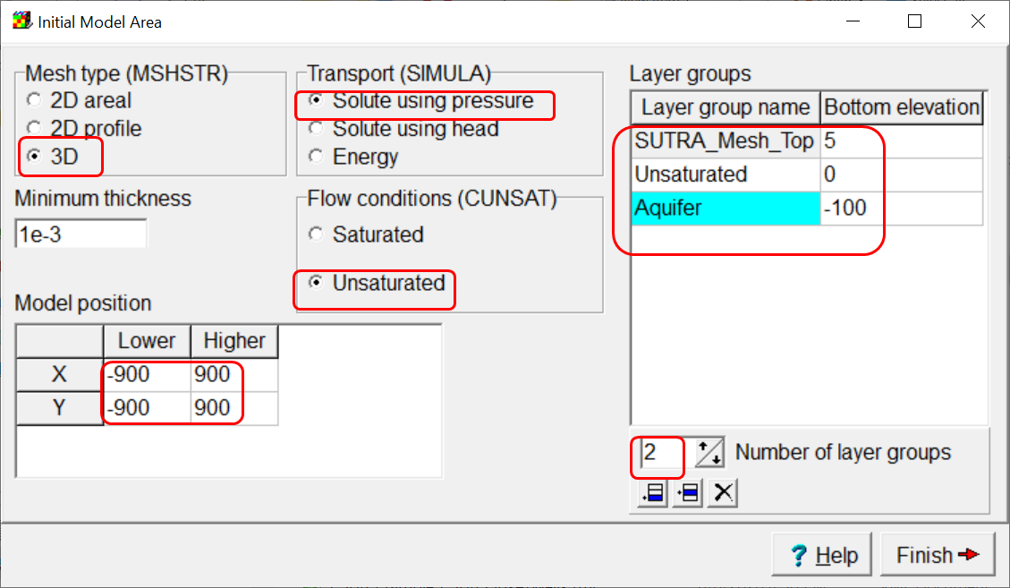
2.Set Mesh type to 3D, and Transport to Simulation using pressure. Set Flow conditions to Unsaturated. Set both the lower X and lower Y coordinates to -900 and the upper X and upper Y coordinates to 900. Set the Number of layer groups to 2. Change the layer group names to Unsaturated and Aquifer respectively. Set the elevations to 5, 0, and -100. Click Finish.
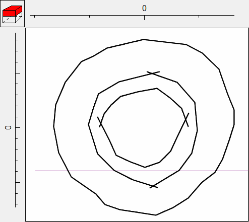
3.Draw a polygon object as a roughly circular region with a radius of 800 m. It can be centered at the origin but it doesn't have to be. This object will define the domain outline. In the Object Properties dialog box, check the Use to set element size check box and set the Mesh element size to 100. Click OK.
4.We need a finer element size near the shoreline at 500 m. However, if we use a polygon object, that polygon will be treated as a hole in the mesh rather than just specifying the element size. However, if we have two intersecting objects (or one object with two intersecting sections) they can define a finer mesh along the shoreline without creating a hole in the mesh. Create polyline objects to define the shoreline and specify a mesh element size of 10. A similar strategy can be used for define a zone with coarser elements within 400 m of the center of the island and a mesh element size of 40. You might end up with objects similar to these.
5.To generate the mesh, select Mesh|Generate Mesh... or click the Generate mesh  button. You can use the default Control variables or change them. Try changing the Element growth rate to 1.1 or 1.2 and then click OK to generate the mesh.
6.You may get a warning message that one or more invalid elements were created. Even if you don't get such a warning, it is a good idea to examine the mesh to make sure it doesn't have any elements that are too narrow. To do that, first zoom in on a small area of the mesh. It doesn't matter where. Then select View|Customize SUTRA Mesh. In the dialog box, check Show element numbers and click Apply. Then select Mesh|View Mesh Information.
7.The angles made by all the element corners will be listed on the Element Angles tab. If there are any angles ≥ 180, there will be two tables on this tab with the elements with angles that are too large listed on one of the tables. Otherwise, there will only be one table. If you click in a table a Go to button will appear. Clicking it will move you to the element listed in the same cell as the button. You can also look at the Aspect Ratios tab where there is a similar table of aspect ratios. You should check some of the elements with the smallest aspect ratios to see if they seem too narrow.
8.If you have any elements that are problematic, you can either edit the mesh manually to fix the problem, adjust the objects used to define the mesh slightly and generate the mesh again, or generate the mesh using different Control variables. It may take some experimentation to generate an acceptable mesh.
9.Next select Model|SUTRA Options. On the Title pane enter a title of your choice. On the Solver pane, choose an iterative solver for both pressure and transport. Click OK to close the SUTRA Options dialog box.
10.Next we will set some of the aquifer properties. Select Data|Edit Data Sets. First select SUTRA Mesh Top under Required|Layer Definition and set its Interpolation method to Natural Neighbor. Set the following formulas for the data sets shown in the table below.
Data Set |
Formula |
Longitudinal_Dispersivity_Max_Dir |
10 |
Maximum_Permeability |
5E-12 |
Minimum_Permeability |
Maximum_Permeability / 10 |
Nodal_Porosity |
0.1 |
Transverse_Dispersivity_Max_Dir |
0.1 |
Unsaturated_Bottom |
SUTRA_Mesh_Top - 5. |
11.The next thing to do is to define the top of the model. We will use interpolation among objects to do that. We can reuse the three objects that define the mesh plus a new fourth object at a distance of 700 m from the center of the island. First double-click on the object that defines the domain outline to open the Object Properties dialog box. On the Properties tab, change Evaluated at to Nodes and the Number of Z formulas to Zero. Uncheck Set values of enclosed nodes and check Set values of nodes by interpolation. On the Data Sets tab, check the check box for SUTRA_Mesh_Top (under Required|Layer Definition) and set the formula to -5. Click OK to close the dialog box. Do the same with the objects that define the interior of the island and the shoreline and use them assign values to SUTRA_Mesh_Top of 5 and 0 respectively. Then create another polygon object that circles the island at a distance of 700 m from its center and use it to assign a value of -5 to SUTRA_Mesh_Top by interpolation.
12.For the next few steps, we will need to use the concentration of seawater in some of our calculations. We will define a global variable to specify the concentration of seawater. Select Data|Edit Global Variables. Name the new variable "csea" and set its value to 0.0357. To remind ourselves of what csea is set the Comment to "Concentration of Seawater."
13.Select Data|Edit Data Sets and set the formula for the InitialConcentration data set to csea
14.We will also need to calculate the specific weight of water, ρg. where ρ is the density or water and g is gravity (9.81). We will define a new data set name RhoG. We can calculate the density of water as (1000. + (700. * csea)) so the entire formula for RhoG would be (1000. + (700. * csea)) * 9.81. Select Data|Edit Data Sets and create a new data set named RhoG. Make sure it is Evaluated at Nodes. Set its formula as described above.
15.Next we want to assign a pressure boundary along the vertical edge of the model and along the top surface of the model where it is beyond the shoreline. For the vertical edge of the model, we want to use the object that defines the domain outline but we can't because we are already using it to define help define the top of the model. To help define the top of the model, the Number of Z formulas must be Zero. For the pressure boundary we will need to set the Number of Z formulas to Two. However, we can make a copy of the domain outline object and change its Number of Z formulas. Select the domain outline object and copy it the the clipboard. Then paste it back from the clipboard.
16.Double-click on the new object to open it in the Object Properties dialog box. On the Data Sets tab, uncheck the check box for SUTRA_Mesh_Top. On the Properties tab, uncheck the Use to set element size check box and the Set values of nodes by interpolation check box. Check the Set values of intersected nodes check box. Set the Number of Z formulas to Two. Set formula for the Higher Z coordinate to "SUTRA_Mesh_Top + 1" and the formula for the Lower Z coordinate to "Aquifer Bottom - 1." (These formulas put the top of the object above the top of the mesh and bottom of the object below the bottom of the mesh so that it doesn't affect any nodes in the interior of the mesh.
17.Next switch to the SUTRA Features tab and check the check box for Specified Pressure. In the table, set the Time to 0, check the check box for the Used column, set the formula for the Specified pressure to "-RhoG * Z," and the formula for the Associated concentration to "csea." Click OK to close the Object Properties dialog box.
18.We want another specified pressure boundary where the model top is in the ocean rather than on shore. We will use a little trick to do this. First, draw a polygon object completely around the mesh. In the Object Properties dialog box, change Evaluated At to Nodes and change the Number of Z formulas to One. Change the formula for the Z coordinate to "If((SUTRA_Mesh_Top <= 0.), SUTRA_Mesh_Top, (SUTRA_Mesh_Top + 1.))." This formula places the object above the top of the mesh over the island but at the top of the mesh under the ocean.
19.Try coloring the grid with the specified pressure to make sure it is being assigned properly. If it isn't, you can use the Grid or Mesh Value dialog box to help figure out what is going wrong.
20.The next thing to do is to set the direction of the maximum permeability. Recall that it should be radiating out from the center of the mesh and downward at an angle of 20°. We are going to need another data set when setting the angles.
21.Select Data|Edit Data Sets and create a new data set named "PermDir." Make sure Evaluated at is set to Elements. Set the interpolation method to Inv. Dist Sq. and (this is important) set the units to "Degrees." By setting the unit to degrees, interpolation will be performed using a special method. Instead of interpolating the raw angles which would often result in bad interpolated values, the sines and cosines of the angles are interpolated and then recombined into an angle at each location where an interpolated angle is needed.
22.Before closing the Data Sets dialog box, select the Angle_Horizontal data set and set its formula to "PermDir." We need to use the intermediate "PermDir" data set because the Angle_Horizontal data set is a 3D data set and interpolation is not allowed on 3D data sets.
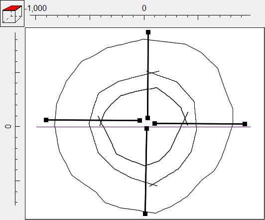
23.Now we are going to create some objects radiating out from the center of the island and use the orientation of these objects to set the direction of maximum permeability. Draw a polyline object with two vertices starting at the center of the island and extending east toward the edge of the island. In the Object Properties dialog box. Set the Number of Z formulas to Zero and on the Data Sets tab, Uncheck Set values of intersected elements and check Set values of elements by interpolation. check the check box for PermDir and set its formula to "ObjectCurrentSegmentAngleDegrees" This function returns the angle of the segment of the object that is being used to set the value of an element or nodel Draw three more polyline objects extending North, South and West and use them to set the value of PermDir in the same way.
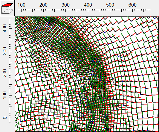
24.To check that the first angle has been set correctly, we can use a vector plot of the permeability. Select Data|Data Visualization... or click the Data visualization  button and go to the Vectors pane. Select Permeability as the Vector Source and click Apply. You should be able to see the vectors on the mesh. If in some areas, the vectors appear completely wrong check that all the objects that are being used to set PermDir set the values of elements by interpolation. You can try experimenting with the interpolation method for PermDir to see how that affects the vectors.
25.Setting the vectors to point downward by 20° can be done in the Data Sets dialog box. Set the formula of the Angle_Vertical data set to -20. The effect on the vectors should be most obvious on the front view of the model.
26.We still haven't subdivided the layer groups into multiple layers. We will do that now. Select Model|SUTRA Layer Groups... Select the Unsaturated layer group and set its Vertical discretization to 5. Select the Aquifer layer group and set its Vertical discretization to 20. Click OK.
27.Save the model with a name that indicates it is being used to specify the initial pressure.
28.Run the SUTRA model (File|Export|SUTRA input files).
29.Save the model again with a different name that indicates it is being used for the transient simulation.
30.Select Model|SUTRA Options and change the Simulation type to Transient flow, transient transport. Go to the Initial Conditions pane and and set the Starting type to Cold start. Check Read the pressure/head from the restart file. Select the restart file generated when you ran the model for the initial pressure. Click OK to close the dialog box.
31.Select Model|SUTRA Time Controls... Set the Maximum number of times after the initial time (NTMAX) to 100 and the Initial time increment TIMEC to 6311520. Click OK to close the dialog box.
32.Select Model|SUTRA Output Control... and set the frequency of printing to both the Listing file and the node and element files to every 25 time steps.
33.Next we need to define the fluid flux boundary. The recharge rate is 2.3766E-5. This needs to be multiplied by the area of the cell surrounding the node to get the volumetric recharge rate. Draw a polygon object completely surrounding the mesh. Set Evaluated at to Nodes and set the Number of Z formulas to One. Set the Z formula to "If((SUTRA_Mesh_Top > 0.), SUTRA_Mesh_Top, (SUTRA_Mesh_Top + 1.))." This formula is similar to the one for the specified pressure boundary on the top of the model except that it causes the object to be above the top of the mesh offshore and at the top of the mesh onshore. Switch to the SUTRA Features tab and check the check box for Fluid Flux. Flux boundaries can't begin at time step 0. They have to begin at time step 1 or later so set the Time for the flux boundary to 6311520. Check the check box in the Used column. Set the formula for the Fluid source to "2.3766E-5 * ObjectIntersectArea" and the Associated concentration to 0. Click OK to close the dialog box.
34.You can color the mesh with the fluid source to make sure it is being applied correctly. Make sure you specify the time as 6311520 or greater.
35.Run the SUTRA model (File|Export|SUTRA input files).
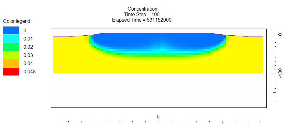
36.When the model is done running import the model results (File|Import|Model Results...  ) and color the mesh with the concentration in the last time step. If you position the cross section through the center of the island, you should see that the fresh water extends deepest not at the center of the island but part way to the edge. This is the result of the maximum permeability sloping downward and away from the center of the island.