Objects (except for point objects) can be used to set the size of elements (PHAST) or cells (MODFLOW) in a grid. Multiple objects can be used in determining the grid location and node spacings. An object drawn on the top view of the model can be used to specify the column and row widths. Polygons drawn on the top view of the model that are used to specify the grid element or cell size also specify the grid location. The grid will be drawn to completely enclose the polygon or polygons. With PHAST, an object drawn on the front or side view of the model specifies the layer height and the vertical extent of the grid. For an object to be used to specify the grid, the Use to set grid element\cell size checkbox in the Object Properties dialog box must be checked. When it is checked, the user can enter the desired size in the Grid element\cell size edit box. The Object Properties dialog box appears when an object is created or when the user double-clicks on an object.
In both PHAST and MODFLOW, having an area with a refined grid can be useful where results need to be more accurate. To support this, ModelMuse allows the user to specify overlapping objects that specify different element sizes. The final sizes of the elements will be determined by the smallest element size specified for a region. In MODFLOW (but not PHAST) it is important that the contrast in element size in adjacent elements not be too large. When the user creates a grid using objects, the Grid smoothing criterion in the Generate Grid dialog box allows the user to specify the maximum ratio of lengths between nodes for adjacent rows, columns, or layers that will be accepted. The default value is 1.2, which is well below the usual limit of 1.5. For Well Footprints, the cells are required to be of uniform size so only one object will be used to define the grid size. With MODFLOW 6 models, another way to refine the grid is to convert to Discretization by Vertices.
The following steps illustrate the creation of grids by using objects.
1.The user draws one or more polygons on the top view of the model to define the grid location and the size of the elements (PHAST) or cells (MODFLOW). For PHAST, the user must also draw a line on the front or side view of the model (fig. 12). In MODFLOW, the vertical discretization is defined in the MODFLOW Layer Groups dialog box. (To create objects, see "Creating, Selecting, and Editing Objects in ModelMuse" and the Object menu item.) In this example, the size of the elements are set in the Object Properties dialog box to 1,000 m in the horizontal direction (top view, fig. 12) and 10 m in the vertical direction (front view, fig. 12).
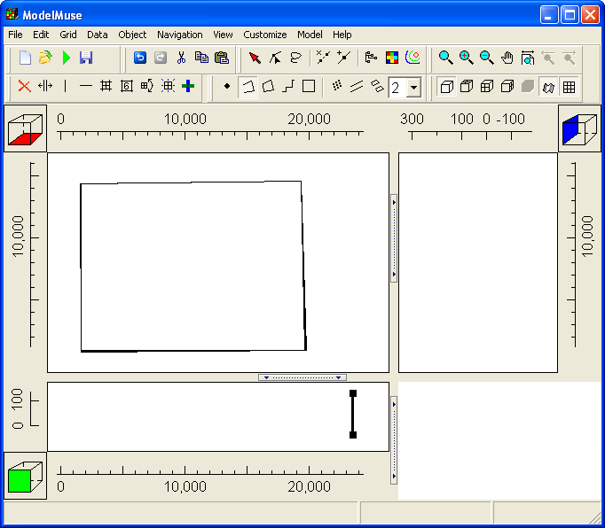 |
Figure 12. Two objects used to define the position of the grid. |
2.The user selects Grid|Generate Grid... or clicks the Generate grid button and the Generate Grid dialog box appears (fig. 13). When the user clicks on the OK button, the grid is created (fig. 14).
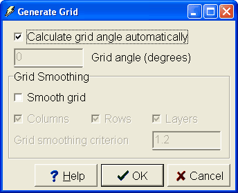 |
Figure 13. The Generate Grid dialog box. |
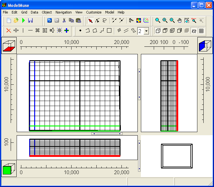 |
Figure 14. Grid and objects. |
3.It may be desirable to have a finer grid in some regions than others. To do this, additional objects can be used to specify a zone where a fine grid will be used (fig. 15). In this example, the object specifies an element size of 200 m in the Grid element size edit box of the Object Properties dialog box.
4.After choosing Grid|Generate Grid... again, a new grid is created with a smaller element size in the area enclosed by the object (fig. 15).
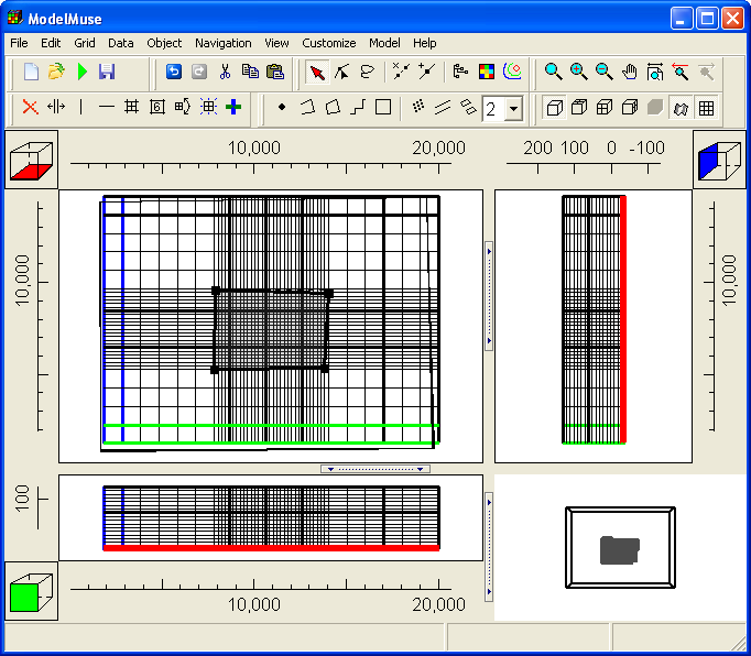 |
Figure 15. Grid with region with smaller elements specified by polygon object. |
5.In some cases, it may be desirable to have a gradual transition in element size. A size transition can be achieved by checking the Smooth grid checkbox in the Generate Grid dialog box (fig. 16). When it is checked, the widths of the columns, row, or layers will be adjusted so that the maximum ratio of the widths of adjacent cells is less than or equal to the grid smoothing criterion. An example of such a grid is shown in figure 17. See "Editing the Grid" for more information on grid smoothing.
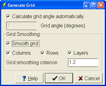 |
Figure 16. Generate Grid dialog box with grid smoothing activated. |
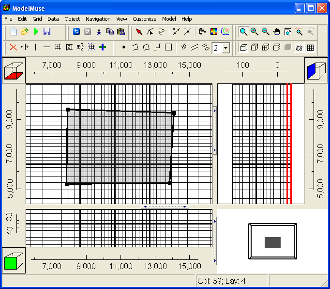 |
Figure 17. Grid generated with grid smoothing. |