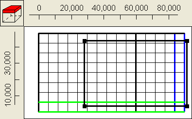
14.The next boundary condition is a specified flux boundary. It occupies the entire top layer to the right of 30000 except for the first and last rows. Draw a polygon that encloses this area (fig. 55). In the Object Properties dialog box, select the Nodes radio button. Set its Name to “Flux_Boundary.” Check the Set values of enclosed nodes checkbox. Set the number of Number of Z formulas to One and set Z-coordinate to 400. On the PHAST Boundary Conditions tab, choose a Flux boundary. Set the Flux for time 0 to -0.055 and set the Associated solution to 1. Click OK to close the dialog box. It is possible to color the grid with Top_Flux_Boundary_Flux to make sure the boundary condition was applied properly. It may be necessary to make the selected layer the top layer to see that the flux is applied properly.

Figure 55. Polygon used to define specified flux boundary in example 3.
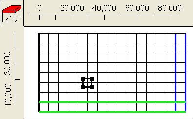
15.The next boundary condition is a specified-head boundary (Lake Stanley Draper, figure 56). On the top view of the model, it looks like the lake only affects one node. However, it actually extends from an elevation of 300 to 400. Thus, it affects two nodes: one in the top layer and one in the layer just beneath it. Draw a polygon surrounding the node at (30,000, 18000) on the top view of the model. In the Object Properties dialog box, select the Nodes radio button. Set its Name to “Lake_Stanley_Draper.” Check the Set values of enclosed nodes checkbox. Set the Higher Z-coordinate to 400 and the Lower Z-coordinate to 300. On the PHAST Boundary Conditions tab, select a Specified head boundary and set the Head to 348 and the Associated solution to 1. Click OK to close the dialog box.

Figure 56. Polygon used to specify the specified-head boundary condition in example 3.