There are two leaky boundaries in the model. Both are in the XZ plane so they are drawn on the front view of the model. One is at the front of the model and extends from the left edge of the model to an X-coordinate of 39000. The other is at the back of the model and extends from the left of the model to an X-coordinate of 29000. Both leaky boundaries extend over the whole extent of the model in the Z direction.
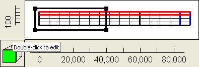
16.For the front boundary draw a rectangle on the front view of the model that goes from the left edge to approximately 39000 and that covers the entire height of the model (fig. 57). In the Object Properties dialog box, select the Nodes radio button. Set its Name to “Front_Leaky_Boundary.” Check the Set values of enclosed nodes checkbox. Set the Number of Y formulas to One. Set the Y-coordinate to 0. On the PHAST Boundary Conditions tab, select the Leaky boundary, set the Hydraulic conductivity to 1.5e-5, the Thickness to 20000, the Head to 320 and the Associated solution to 2. Click OK to close the dialog box.

Figure 57. Polygon used to specify the leaky boundary on the front view of the model in example 3.
17.For the back boundary draw a rectangle on the front view of the model that goes from the left edge to approximately 29000 and that covers the entire height of the model. In the Object Properties dialog box, select the Nodes radio button. Set its Name to “Back_Leaky_Boundary.” Check the Set values of enclosed nodes checkbox. Set the Number of Y formulas to One. Set the Y-coordinate to 48000. On the PHAST Boundary Conditions tab, select the Leaky boundary, set the Hydraulic conductivity to 1.5e-5, the Thickness to 30000, the Head to 305, and the Associated solution to 1. Click OK to close the dialog box.
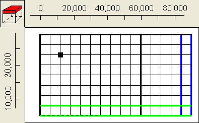
18.The next boundary condition is a well located at (X, Y) = (12000, 36000). Make a point object on the top view of the model at that location (fig. 58). In the Object Properties dialog box, select the Nodes radio button and Name the object “Well.” Check the Set values of intersected nodes checkbox. On the PHAST Boundary Conditions tab, select the Well boundary, set the Well name to "Observation well 1 in arsenic zone," set the Diameter to 2, the First elevation to 90, the Second elevation to 110, the Pumping rate to 1, the and the Solution to 1. Make sure the Allocate by pressure and mobility checkbox is unchecked. Click OK to close the dialog box.

Figure 58. Point object used to specify well boundary in example 3.