The next step is to import the image of the Rocky Mountain Arsenal area. Select File|Import|Image... and the Import Image dialog box will appear. Click the Select Image button and select the file "rmamap.emf" (in the "Users|Public|Public Documents\ModelMuse Examples\data\RMA" folder). The user will be prompted to click on the image and enter the real-world coordinates of the points that was clicked. Entering the coordinates allows the image to be georeferenced so it can be displayed at the correct location. The coordinates to be entered are in the table below.
Pixel X |
Pixel Y |
X |
Y |
7 |
0 |
1688 |
9037 |
402 |
545 |
6300 |
2639 |
The image will appear in the top view of the model. Click on the Zoom button  and click and drag a rectangle around the image. When the mouse button is released, ModelMuse will zoom in on the selected area. Try experimenting with the Pan button
  . Click the Pan button and then move the mouse over the top view of the model. Push down the mouse button and hold it down. Move the mouse and then release the mouse button. The view of the model should be dragged to a new location when this is done. Try experimenting with the Zoom In
  and Zoom Out
  buttons too. When one of those buttons is clicked, clicking on the model will zoom in or out by a factor of two at the location that was clicked. See the help for the Navigation menu for more details.
It is possible to draw objects to define the entire model. However, it is easier to import them if they have already been defined elsewhere. In this case, there is a Shapefile that contains the objects needed to define much of the model. The next step is to import the Shapefile.
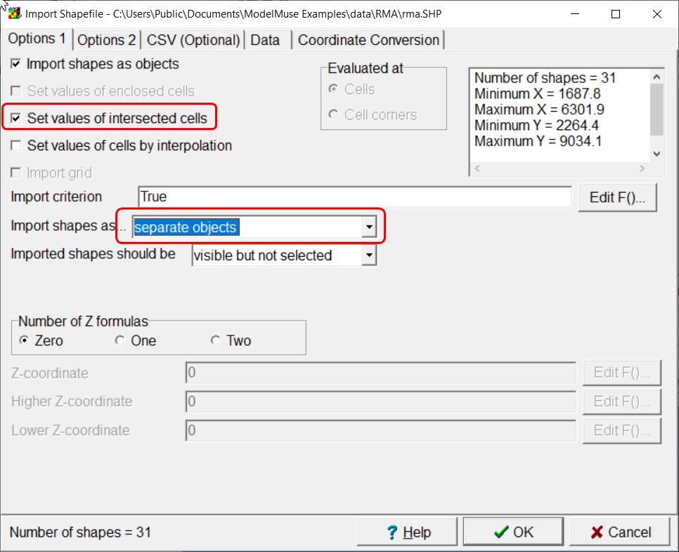
Select File|Import|Shapefile... Select rma.SHP. (in the "My Documents\ModelMuse Examples\data\RMA" folder.) Check the Set values of intersected cells check box and import the shapes as separate objects (fig. 98). The attributes associated with the shapes aren't useful so there is no need to check the check box under "Import" in the table on the Data tab. Instead, just the geometry of the shapes will be imported. Click the OK button.

Figure 98. Import Shapefile dialog box showing settings.
The shapes may not be visible at first because they are at the hidden by the image. To hide the image, select Edit|Show or Hide Image
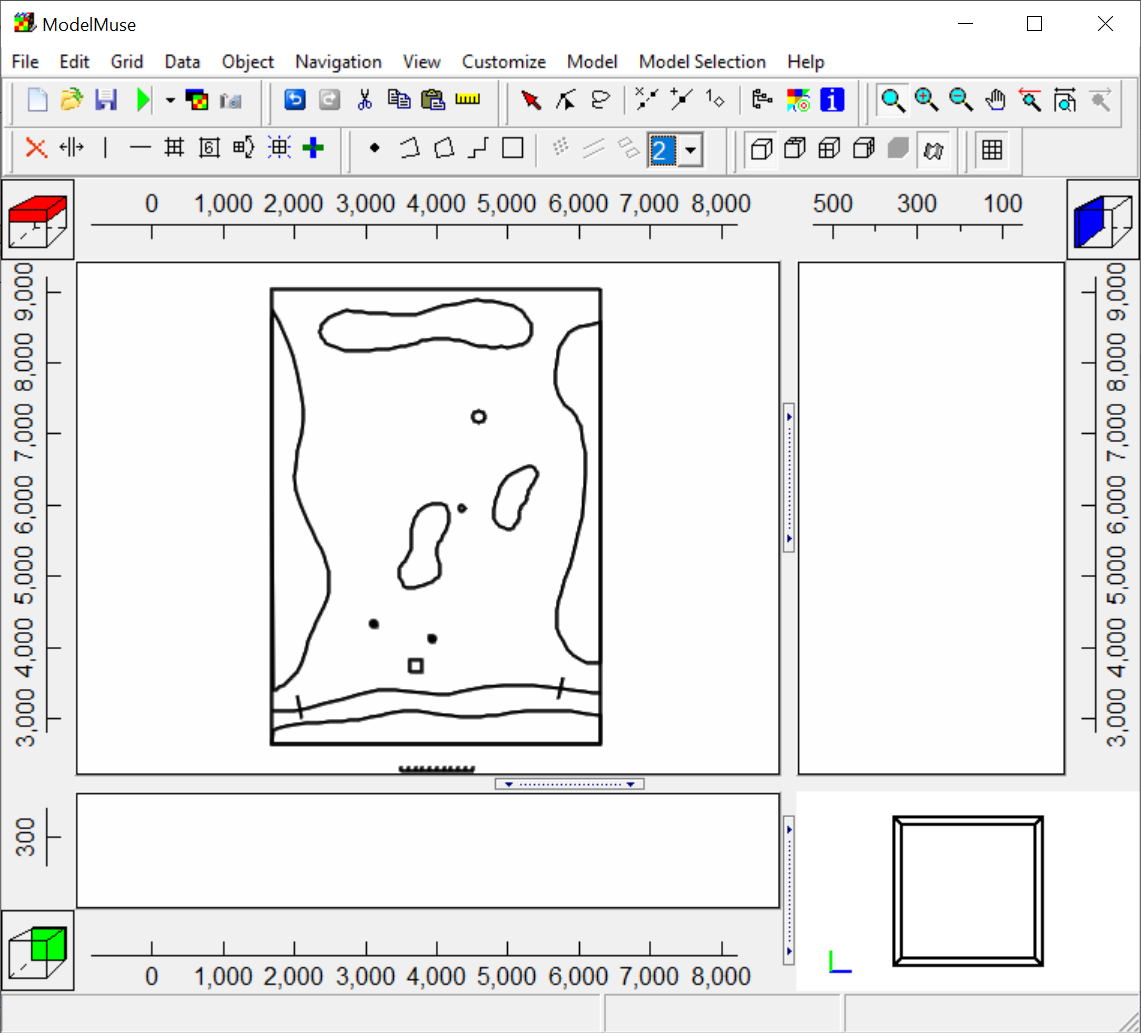
The model will now appear similar to figure 99. Show the image again by selecting Edit|Show or Hide Image again.

Figure 99. Model after importing Shapefile with data.