There are two specified head boundaries. One is on the left end of the model and the other is on the right. The one on the left has a head of 1 and an associated solution with an index of 2 from time 0 to time 60. For the rest of the duration of the model, it has an associated solution with an index of 1. The boundary on the right side has a head of 0.0 and an associated solution of 1.
9.First zoom in on the left side of the model by selecting Navigation|Zoom In and then clicking on the left side of the top view of the model (fig. 41).
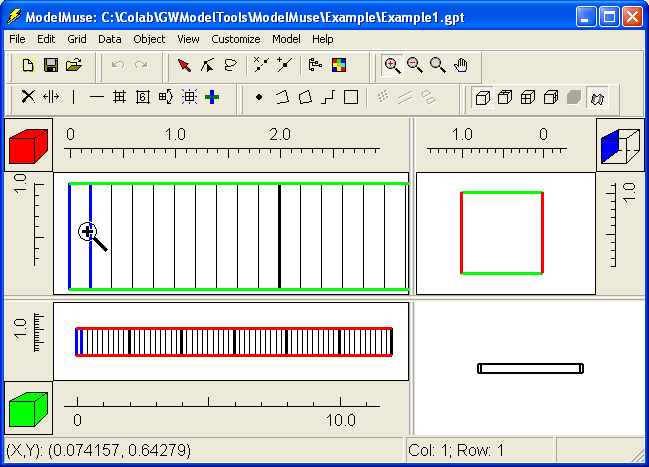
Figure 41. Appearance of model in example 1 after zooming in on the left side of the top view of the model.
10.The next step is to create the boundary condition on the left side of the model. Select Object|Create|Straight Line. Click on the top view of the model and then click again to draw a line near the left end of the model (fig. 42). Double-click or push the Enter key on the keyboard to finish drawing the line.
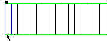
Figure 42. Drawing a line near the left side of the top view of the model.
11.At this point the Object Properties dialog box will appear. Click the Help button and read about this dialog box. On the Properties tab, check the Nodes radio button. Then change to the PHAST Boundary Conditions tab and select the Specified head radio button. Change the Number of times (beneath the list of boundary types) to 2. Then fill in the table for the specified-head boundary condition as illustrated in figure 43. This specified-head boundary will have a Head of 1 for the duration of the model but its Associated solution will change from 2 to 1 after 60 seconds. The value for Head only needs to be specified once.
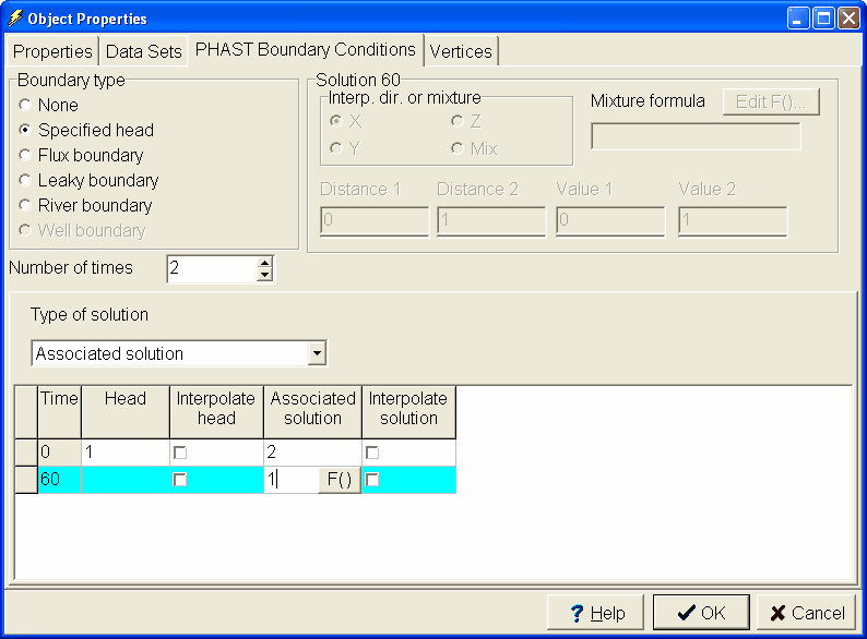
Figure 43. Object Properties dialog box showing how to set up the specified-head boundary for the left side of the model.
12.On the Properties tab, make sure that the Set values of intersected nodes checkbox is checked. Also check that the Higher Z-coordinate is 2 and the Lower Z-coordinate is 0. This means that the line is a vertical surface with a top of 1 and a bottom of 0. Click the OK button. That completes setting up the specified-head boundary for the left side of the model.
13.Click with the mouse on the 3-D view of the model and drag with the mouse button held down to rotate the 3-D view. Note that on the left side there is a gray shape representing the 3-D vertical surface (fig. 44).
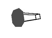
Figure 44. Three dimensional view of model showing object on left side of model.
14.The next step is to create the specified-head boundary on the right side of the model (fig. 45). Select Navigation|GoTo... and change to the Element tab. Uncheck the checkboxes for Front and Side. Change Column to 60 and click the OK button. The right end of the model should now be visible in the top view of the model. Again select Object|Create|Straight Line and draw a line on the right side of the top view of the model. Again select the Nodes radio button and check the Set values of intersected nodes checkbox. On the PHAST Boundary Conditions tab, select a Specified head boundary and set the Head to 0 for time 0 and the Associated solution to 1. Click the OK button. This Specified head boundary will have a Head of 0 for the duration of the model and an Associated solution of 1.
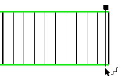
Figure 45. Drawing a line to represent a specified-head boundary on the right side of the top view of the model.