MODFLOW 6 Example: Define Specified-Head Boundary |
MODFLOW 6 Example: Define Specified-Head Boundary |
The next step is to represent a lake in the upper right corner with a specified-head boundary in the top layer.
1.We don't need to work with the objects that define the thickness of the middle aquifer any more so use the Show or Hide Objects dialog box to hide them.
2.Use the Model Cube  to select the top layer. This ensures that when we create the object, the formulas for the higher and lower Z formulas will be the ones for the top and bottom of the top layer.
3.Change the value in the "Number of elevations in new objects" combo box from 0 back to 2.
4.Click the "Create polygon object" button  and create a polygon on the top view of the model that surrounds several active cells in the upper right corner of the grid. This polygon will represent the lake. When you double-click to complete the polygon, the Object Properties dialog box will appear.
5.In the Object Properties dialog box, make sure the the formulas for the higher and lower Z coordinates are "Model_Top" and "Upper_Aquifer_Bottom" respectively so that the object applies to cells in the top layer.
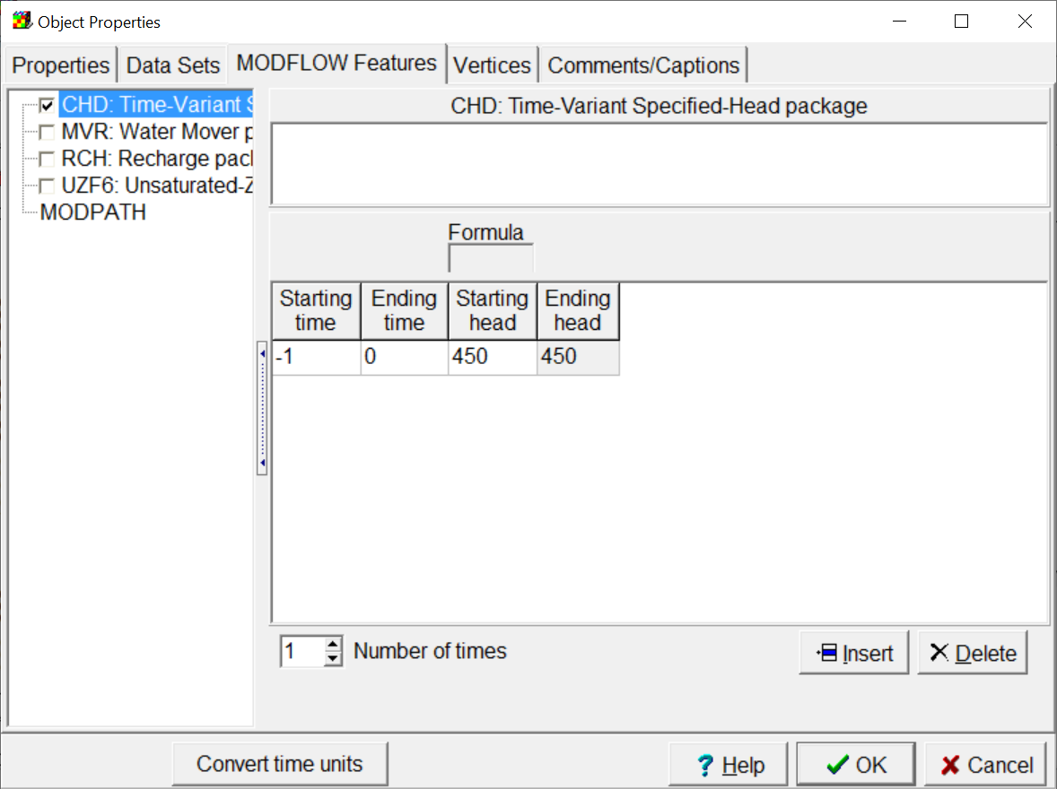
6.On the MODFLOW Features tab, check the check box for the CHD package, set the starting and ending times to -1 and 0 respectively. (By default, ModelMuse defines an initial steady-state stress period extending from -1 to 0.) Set the starting and ending heads to 450. (If the starting and ending heads are set to different values MODFLOW will interpolate the heads between them in each time step.)

Specifying the starting and ending heads for the CHD package.
7.Click OK to close the dialog box.
8.(Optional) If you wish, you can try coloring the grid the CHD ending head. The cells inside the object should end up colored green.