|
Generating the Grid |
|
Generating the Grid |
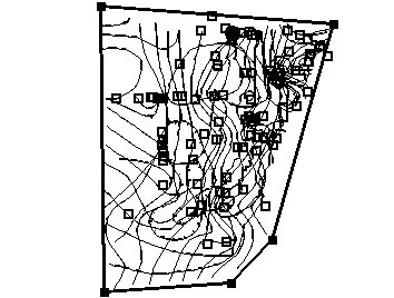
18.The next step is to draw a domain outline around the area to be modeled. Select Object|Show or Hide Objects… Check the checkbox next to All Objects so that all objects are visible. Select Object|Create|Polygon and draw a polygon on the top view of the model that roughly surrounds all the objects (fig. 60). In the Object Properties dialog box, set the Name to “Domain_Outline“, check Use to set grid element size and set the Grid element size to 2500. Click OK to close the Object Properties dialog box. It is no longer necessary to see the imported objects so in the Show or Hide Objects dialog box, uncheck the checkbox next to Data Sets to hide them all. (It may be necessary to display the Show or Hide Objects dialog box if it is hidden behind the main ModelMuse window.)

Figure 60. Domain outline for Biscayne Bay aquifer model.
19.To define the vertical extent and element size of the grid, draw a vertical line object on the front view of the model (figure 5) using Object|Create|Straight Line. The model extends from 9 to -271 feet so when the Object Properties dialog box appears set the Z coordinates to 9 and -271 in the Vertices tab. Set the Name of the object to “Side_Domain_Outline.” Check Use to set grid element size and set the Grid element size to 28. Click OK to close the dialog box.
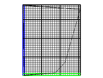
20.To create the grid (fig. 61), select Grid|Generate Grid..., uncheck Calculate grid angle automatically and click the OK button.

Figure 61. Grid in Biscayne Bay aquifer example.