Sampling Ground Water For CFCs - Ampoules (OLD METHOD)
Field Instructions for ground-water sampling
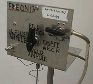
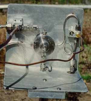
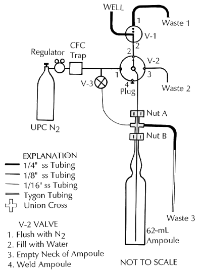
Figure 1
Initial Gas Flow Checks
Attach the ultra-pure nitrogen to 1/8" Swedgelock fitting on the back of the apparatus.
1. Loosen nut A (Figure 1) and slide the union-cross up the 1/8" ss tubing to near the top of the apparatus. Now tighten nut A.
2. Loosen nut B and insert ampoule then tighten nut B. (If the ampoule is not held firmly, then wrap some good quality Teflon tape around the ampoule neck to increase its diameter).
3. Rotate V2 to position 4 [WELD, Ampoule]. Place Tygon tubing (Waste 3) in a cup of water. Gas flow should be about 30-80 cc per minute. The gas flow was adjusted and checked before shipment of the apparatus. If there is excessive gas flow, you will not be able to weld the ampoule because the flow will over pressurize the apparatus. Low gas flow may allow air to enter the apparatus. The gas flow can be adjusted by means of needle-valve V3. Do not over-tighten this valve, once it is set you do not have to re-adjust it at every well.
4. Rotate V2 to position 1 [N2 FLUSH, Ampoule]. Gas flow at this position should be at least 200 cc per minute. This flow is used to purge the air out of the ampoule. This flow can be altered by changing the pressure on the nitrogen gas regulator. A pressure of about 25 psi is normally sufficient to provide the proper gas flows through the CFC apparatus.
Set-Up of the Apparatus
At each new well, set-up the apparatus by connecting the water to the 1/4" Swedgelock fitting and the ulta-pure nitrogen to the 1/8" fitting. Before sampling, purge the well (standard procedure is 3 casing volumes). After purging,
(a) allow water to flow through the 1/4" tubing and V1 to WASTE 1 (V1 set at position 1 [Waste]), then
(b) allow well water to flow though the tubing and valves to remove any residual water from the previous well. This is done by setting V2 to position 2 [FILL, Water] and turning V1 from position 1 [Waste] to 2 [Water]. Water will flow through the 1/8" tubing. Allow this flow for several minutes to clean the system.
Sampling Ground Waters for CFC's
1. Loosen nut A and slide the union-cross up the 1/8" ss tubing to near the top of the apparatus. Now tighten nut A.
2. Rotate V2 to position 1 [N2 FLUSH, Ampoule]. Any water that may be in the valve will be forced out of the 1/8" ss tubing.
3. Loosen nut B and inset ampoule then tighten nut B. (If the ampoule is not held firmly, then wrap good quality Teflon tape around the ampoule neck to increase its diameter, insert the ampoule and tighten nut B).
4. Allow at least one minute to purge the ampoule of air.
5. Turn V2 from position 1 to position 2 [FILL, Water] and then turn slowly V1 from position 1 [Waste] to position 2 [Water]. The ampoule will start filling with water. When it is full, the over-flow will mix with nitrogen in the union-cross and go to Waste 3. Allow the over-flow to continue for more than 5 ampoule volumes.
6. Loosen nut A and lower the union-cross until the 1/8" tubing is in the lower part of the neck of the ampoule while water is still flowing through the 1/8" tubing (Point C, fig. 1). Tighten nut A.
7. Turn V1 to position 2 [Waste].
8. Wait until no more water is coming across the union-cross into Waste 3.
A. First pinch the Tygon tubing leading to Waste 3.
B. Now turn V2 from position 2 to 3 [EMPTY, Neck]. The neck of the ampoule should empty of water.
C. Turn V2 from position 3 to 4 [WELD, Ampoule] and release the pinched tygon tube.
9. Loosen nut A and lower union-cross until 1/8" ss tubing is outside the neck of the ampoule. Tighten nut A.
10. Weld ampoule closed with oxygen-MAPP gas torch. (If bubbles in glass form, check and determine if the Tygon discharge tube [Waste 3] end is in water causing an increase in pressure in the apparatus).
11. The ampoule remains hot for a long time! Check for pin-holes after the ampoule has cooled.
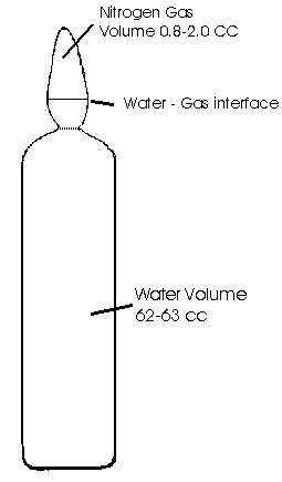
Figure 2