Analytical Procedures for CFCs
In This Document
- Preservation of Samples
- Sample Ampoule Headspace
- Apparatus for Measurement of CFCs
- Introduction of Water into the Stripping Cell
- Measurement Procedures
- Blanks
- Standards and Calibration
- Instrument Stability and Drift
- References
CFCs are determined in the laboratory using a purge-and-trap gas chromatography procedure with an ECD detector. This section describes details of the measurements, including preservation of samples, determination of the gas volume in the headspace of the ampoule, the apparatus for measuring CFC-12, CFC-11 and CFC-113 concentrations, the procedure for introducing the water into the stripping cell, the measurement procedure, blanks, standardization and calibration procedures, and instrument stability.
Preservation of Samples
Prior to the development of storage procedures by Busenberg and Plummer [1992], storage of water samples without contamination of halocarbons was difficult. Samples can be affected in four ways during storage including sorption to the container surface, reaction with the container surface (including microbial degradation), contamination by the container, and contamination by grease or oil present on the container surface.
Uptake of halocarbons by the container materials can alter CFC concentrations during storage. Reynolds et al. [1990] investigated ten materials, including 316 stainless steel. Significant uptake of halocarbons occurs in aluminum (1-6 hours), stainless steel (1-2 weeks), copper (1-6 hours), galvanized steel (<1 hour), and Nylon (5 minutes). No uptake of halocarbons was evident after 5 weeks in borosilicate glass [Reynolds et al., 1990]. Reynolds et al. [1990] found that the CFC-12 and CFC-11 concentrations of natural waters in welded borosilicate-glass ampoules remained unchanged even after 1 year of storage. The USGS CFC laboratory used borosilicate-glass ampoules for sample collection until about 2004. An alternate and simple method of collection in glass bottles with aluminum foil lined caps has been developed. Storage time of samples in bottles is limited to about six months. In either method, no actual chemical preservatives such as hydrochloric acid are used for fear that the chemical preservatives would contain CFCs.
Storage of waters with trace concentrations of CFCs can result in the contamination of the sample with CFCs if latex rubber, synthetic rubber, silicon rubber, plastics, Teflon, polymers, or grease and oil are in contact with the sample [Busenberg and Plummer, 1992; Reynolds et al., 1990]. For example, significant amounts of CFCs are dissolved in polymers that can seriously contaminate the samples [Reynolds et al., 1990; Bullister, 1984]. In addition, CFCs can diffuse from the air through the polymers into the sample [Bullister, 1984].
Sample Headspace
The CFC content of the aquifer sample is partitioned between the water and the gas in the neck of the ampoule. The bottles also will form a headspace as the sample warms up. Our analytical procedure determines the CFC content of the water in the sample. A correction is applied to account for the CFC content of gas in the headspace of the container. The volume of the headspace in the neck of the ampoule is calculated from the weight of water required to fill the void space. The headspace volume in the bottle is determined by measuring the diameter of the bubble in millimeters. We have calibrated the diameter of the bubbles with injections of a known volume of gas. The headspace is independently evaluated for every sample as part of the CFC analysis. The concentrations of CFC-11, CFC-12, and CFC-113 in the aquifer are calculated from the concentrations in the water sample, the water temperature, and the volumes of water and headspace in the ampoules or bottles. [see for example, Pankow, 1986; 1990].

Figure 2. The CFC analytical system used to pre-concentrate and determine CFC-12, CFC-11, and CFC-113 concentrations. See text for details.
Apparatus for Measurement of CFCs
The CFC analytical system (Figure 2) was modified from the original design of Bullister and Weiss [1988]. Some of the changes include: (1) An additional gas tank and regulator were added in order to make the carrier- and stripping-gas flow separate. This reduces the number of times the ECD must be shut down to change gas tanks since the stripping-gas tank can be isolated from the ECD when it is changed. Ultra-pure N2 is used as the stripping gas and the carrier gas. The blank-gas supply was connected after the gas-pressure regulator of the stripping-gas supply to monitor the quality of the stripping gas. (2) An additional desiccant tube of Mg(ClO4)2 was added after the stripper. The gas flow is rerouted through V4 during the changing of this desiccant tube to reduce the frequency of replacing the desiccant tube between valves V4 and V6 and the complications resulting from the interruption of the gas flow through the system. (3) In order to have better control during the filling and emptying of the stripper cell, the inlet valve (V5) was replaced by two 3-way valves (Figure 2). After gas-stripping is complete, the water sample is drained into a preweighed plastic beaker and then weighed. Bullister and Weiss [1988] use calibrated syringes to fill the stripping cell and determine the volume of the water sample. (4) A flowmeter was added after V7 to continuously monitor the stripping-gas flow through the system.
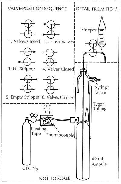
Figure 3. Valves used to inject water samples into the gas-chromatograph system without contamination with air. See text for details.
Introduction of Water into the Stripping Cell
Contamination of samples is a major concern, because introduction of as little as 0.01 cm3 of modern air during sampling is detectable and can be a serious problem with older water samples. Figure 3 shows the procedures and valves used to transfer the water samples from the ampoules to the stripping cell to minimize contact with the laboratory atmosphere.
The prescored ampoule is inserted into the Tygon sleeve as shown in Figure 3. Several liters of ultra-pure N2 that has been further purified by passing through an MS13X trap are passed through the Tygon sleeve and released into the laboratory by means of the syringe valve while the intake valve of the stripping cell is closed (position 1). This procedure removes all the air from around the neck of the ampoule. Next, the syringe valve is closed and the intake valves are turned to position 2 so that the intake valves are flushed with ultra-pure N2 gas. The borosilicate ampoule is broken along the prescored neck by bending the Tygon tube, the union nut is loosened slightly, and the stainless-steel tube is lowered to the bottom of the ampoule. The union nut is immediately tightened, allowing further flushing of the intake valves with about 15-20 mL of sample, which is disposed of in the waste receptacle. The intake valves are now turned to position 3, filling the stripping cell with the sample (about 25-35 mL). When the desired volume of sample is introduced into the cell, the intake valves are turned to position 2, emptying the rest of the sample into the waste receptacle. Samples from bottles are done in much the same way. The cap is removed from the bottle in open air and then the bottle is placed into an adaptor in the tygon sleeve. The sample is taken from the bottom of the bottle in the same procedure as for an ampoule and the stripping cell is filled. The stripping of the water sample begins at this point and continues for the next 4 minutes. After the CFC trap is isolated, the syringe valve is opened and the intake valve is turned to position 4. The empty ampoule is removed and replaced by a new ampoule in preparation for the analysis of the next sample. After stripping the water sample for 4 minutes, the intake valves are turned to position 5, emptying the cell into a preweighed beaker; the intake valves are then closed (position 6). The chromatography phase then begins and continues for the next 6 minutes. The weight of the water is recorded to the nearest 0.01g.
Measurement Procedures
The purged CFCs are quantitatively collected in a cold trap consisting of a column of Porapac-T and Porasil-C held at -30 °C. The CFCs are released by heating this trap to 95°C. Initial separation of the CFC-12, CFC-11, and CFC-113 from other halocarbons takes place in a precolumn of Porasil-C. After CFC-12, CFC-11, and CFC-113 pass through the precolumn into the Porasil-C column (40 seconds), the carrier gas flow in the precolumn is reversed through valves V6 and V7. This procedure prevents other CFCs and halocarbons with higher retention times from entering the analytical column, back-flushes the precolumn and, thus, significantly decreases the analysis time to about 7 minutes. The concentrations of CFC-12, CFC-11, and CFC-113 are measured with an ECD. Measured concentrations are very small- picog/kg or 10-12 g/kg. Standard deviations are 3% at 20picog/kg or more, and ~50% at the detection limit of 0.5-1.0 picog/kg. The analytical procedures used here are described in great detail by Bullister [1984], and Bullister and Weiss [1988].
Blanks
Gas and water blanks are used extensively. The gas blanks of carrier or stripping gas are passed through the gas-sampling loops into the cold trap. The purpose of this procedure is to determine that the instrument is free of contamination. Usually no CFC-12, CFC-11 or CFC-113 signal is obtained from the gases. If a small CFC-12 blank is obtained, it is an indication that the molecular-sieve traps (MS13X), through which the ultrapure gases are further purified, need to be regenerated. The traps are regenerated by heating at 200°C for 4 hours as specified by Bullister and Weiss [1988]. Water blanks are analyzed on an as needed basis and consist of old ground water flame sealed in borosilicate glass ampoules. The water blank is introduced into the stripping cell of the analytical system and analyzed in the same manner as a regular sample. No CFC-12, CFC-11, or CFC-113 signals are normally observed from these water blanks.
Standards and Calibration
The instrument is calibrated with Standard Marine Oregon Air (Oregon Graduate Center) and Niwot Ridge Colorado Air (CMDL of NOAA). The primary standard is an Oregon air sample that was calibrated by Ray Weiss at the Scripps Institution of Oceanography (SIO). Other standards shown below are secondary standards intercalibrated on the SIO scale. Concentrations of standards used in the USGS CFC laboratory in parts per trillion volume are:
| Tank 0 | Tank 1 | Tank 2 | NOAA Tank | |
|---|---|---|---|---|
| CFC-12 | 501.5 | 538.2 | 529.5 | 524.1 |
| CFC-11 | 265.6 | 272.5 | 268.7 | 271.3 |
| CFC-113 | 81.2 | 83.4 | 82.4 | 87.7 |
Standards are stored in electropolished passivated stainless steel tanks or Aculife-treated aluminum tanks.
For an initial calibration at the start of each day, purge gas is injected to provide an instrument blank, then 0, 1, 3, 5, 8, 13, and 21 cc of standard gas are injected. At the end of the day, 5 and 8 cc air standards are run to check instrument stability and to determine instrument drift corrections.
The GC is calibrated in the following concentration ranges:
- CFC-11 from 0-1200 picog/kg
- CFC-12 from 0-2500 picog/kg
- CFC-113 from 0-900 picog/kg
Above these concentrations, the instrument is not calibrated. Saturation of the ECD occurs at high concentrations resulting in the clipping of peaks. Uncontaminated ground water falls within the 0 to 8 cc concentration range of the standards.
Instrument Stability and Drift
- CFC-12 drift is typically less than 1 % in 8 hours
- CFC-11 drift is typically about 1% in 8 hours
- CFC-113 drift is typically 1-3% in 8 hours
Samples that are contaminated cause large drifts. After such contamination occurs, the instrument needs to flush overnight to recover. In extreme cases, the detector and valve rotors can be contaminated. This can cause a week or more of down time.
References
Bullister, J. L., 1984, Atmospheric chlorofluoromethanes as tracers of ocean circulation and mixing: Studies in the Greenland and Norwegian seas, Ph.D. dissertation, 172p. Univ. Calif., San Diego, La Jolla.
Bullister, J. L., and Weiss, R. F., 1988, Determination of CFC3F and CCl2F2 in seawater and air, Deep Sea Res., 35, 839-854.
Pankow, J. F., Magnitude of artifacts caused by bubbles and headspace in groundwater determination of volatile compounds in water, Anal. Chem., 58, 1822-1826, 1986.
Pankow, J. F., Minimization of volatilization gasses during sampling and analysis of volatile organic compounds, p. 73-86. In: Significance and Treatment of Volatile Organic Compounds in Water Supplies, N. M. Ram, Christman R. N. and K. P. Cantor (Eds.), Lewis Publishers, Inc., Chelsea, Michigan, 1990.
Rasmussen, R. A. and M. A. K. Khalil, Interlaboratory comparison, preparation, and stability of dichlorofluoromethane samples and standards, Anal. Chem., 55, 1834-1836, 1983.
Rasmussen, R. A., and Khalil, M. A. K., 1983, Atmospheric trace gases at the South Pole, Antarct. J., U.S., 18, 250-252.
Reynolds, G. W., Hoff, J. T., and Gillham, R. W., 1990, Sampling bias caused by materials used to monitor halocarbons in groundwater, Environ. Sci. Technol., 24, 135-142.