FOR EACH SIMULATION
|
Data Set 0
|
[#Text]
Item 0 is optional - # must appear in column 1. Item 0 can be repeated multiple times.
|
Data Set 1
|
the text “LGR” needs to be entered in the first item to indicate to MODFLOW-LGR that the LGR capability is used.
|
|
Data Set 2
|
the total number of grids used in this simulation, including the parent grid and all of the child grids.
|
|
FOR THE PARENT GRID (the parent grid needs to be listed before the child grid)
|
Data Set 3
|
the name of the Name File for the parent grid. The name can include the file path and is limited to 200 characters.
|
|
Data Set 4
|
GRIDSTATUS is a character variable and indicates whether the file listed in NAME FILE corresponds to a parent or child grid.
| • | If GRIDSTATUS = PARENTONLY, then it is a parent grid Name File. |
| • | If GRIDSTATUS = CHILDONLY, then it is a child grid Name File. |
|
|
Data Set 5
|
IUPBHSV IUPBFSV
A number greater than zero that corresponds to the unit number where the boundary heads are saved for later use by the BFH Package for independent simulations. A file with this unit number needs to be opened in the Name File of the parent model. A value of zero indicates that the file is not written. For the parent model, these are the complementary boundary conditions (see Appendix 2 of Mehl and Hill, 2005).
|
A number greater than zero that corresponds to the unit number where the boundary fluxes are saved for later use by the BFH Package for independent simulations. A file with this unit number needs to be opened in the Name File of the parent model. A value of zero indicates that the file is not written. For the parent model, these are the coupling boundary conditions (see Appendix 2 of Mehl and Hill, 2005).
|
|
|
FOR EACH CHILD GRID [repeat items 6 through 15 for each grid with the exception of the parent grid. That is, repeat these items a total of (NGRIDS - 1) times]
|
Data Set 6
|
the name of the Name File for the child grid. The name can include the file path and is limited to 200 characters.
|
|
Data Set 7
|
GRIDSTATUS is a character variable and indicates whether the file listed in NAME FILE corresponds to a parent or child grid.
| • | If GRIDSTATUS = PARENTONLY, then it is a parent grid Name File. |
| • | If GRIDSTATUS = CHILDONLY, then it is a child grid Name File. |
|
|
Data Set 8
|
ISHFLG IBFLG IUCBHSV IUCBFSV
ISHFLG is a flag indicating whether heads from the parent grid simulation should be used as the starting head for the child grid simulation. These heads apply to the interior of the child, not the boundary.
| • | If ISHFLG = 1, then use results of the parent grid simulation as the starting head for the child grid. In the cells of the child grid that overlap the parent grid, the heads of the corresponding parent cell are used. No interpolation is applied. For steady-state simulations, this can provide a good initial guess which can reduce computational time. For transient simulations, this overwrites the initial condition of the child model defined in STRT of the Basic Package input file (Harbaugh, 2005) and, therefore, is not recommended. |
| • | If ISHFLG = 0, then use the heads defined in STRT of the Basic Package for the child grid. |
|
IBFLG is a integer used to define the interface of the child grid with the parent. Use this value around the perimeter of the child model IBOUND array. Do not use IBFLG or -IBFLG anywhere else in the parent or child IBOUND arrays. Use a unique value for each child grid.
In MODFLOW-LGR version 1, IBFLG is a negative integer.
In MODFLOW-LGR version 2 and MODFLOW-OWHM, IBFLG is a positive integer.
|
IUCBHSV – A number greater than zero that corresponds to the unit number where the boundary heads are saved for later use by the BFH Package for independent simulations. A file with this unit number needs to be opened in the Name File of the child model. A value of zero indicates that the file is not written. For the child model, these are the coupling boundary conditions (see Appendix 2 of Mehl and Hill, 2005). Note: the boundary heads are only saved if two-way coupling is used. (MXLGRITER > 1)
|
IUCBFSV – A number greater than zero that corresponds to the unit number where the boundary fluxes are saved for later use by the BFH Package for independent simulations. A file with this unit number needs to be opened in the Name File of the child model. A value of zero indicates that the file is not written. For the child model, these are the complementary boundary conditions (see Appendix 2 of Mehl and Hill, 2005). Note: the boundary fluxes are only saved if two-way coupling is used. (MXLGRITER > 1)
|
|
|
Data Set 9
|
MXLGRITER IOUTLGR
MXLGRITER is the maximum number of LGR iterations; 20 iterations are sufficient for most problems. See Closure Criteria for LGR Iterations section of the report by Mehl and Hill (2005). Set MXLGRITER to 1 for a one-way coupling.
|
IOUTLGR is a flag that controls printing from LGR iterations of the maximum head and flux change. For the maximum head change, the head value and corresponding layer, row, and column of the child grid is listed. For the maximum flux change, the flux value and corresponding layer, row, and column of the parent grid is listed.
| • | If IOUTLGR < 0, output is written to the screen. |
| • | If IOUTLGR > 0, output is written to the child listing file. |
| • | If IOUTLGR = 0, no results are written. |
|
|
|
Data Set 10
|
RELAXH RELAXF
RELAXH – is the relaxation factor for heads.
|
RELAXF – is the relaxation factor for fluxes.
|
Values of RELAXH and RELAXF less than 1 and greater than zero are needed for convergence of the LGR iterations. Typically, values around 0.5 produce convergent solutions. Values less than 0.5 may be needed when the LGR iterations have difficulty converging. In cases in which the LGR iterations exhibit no convergence difficulties, values greater than 0.5 may reduce the number of iterations needed for convergence. Convergence difficulties can be diagnosed by printing the maximum head and flux changes (IOUTLGR ≠ 0) to determine if the head and flux changes are decreasing (converging) or increasing (diverging) as the LGR iterations proceed.
|
|
Data Set 11
|
HCLOSELGR FCLOSELGR
the head closure criterion for the LGR iterations. The closure criterion is based on heads of the child-interface nodes. This closure criterion is satisfied when the maximum absolute head change between successive LGR iterations is less than HCLOSELGR (see equation 8b of the LGR documentation, Mehl and Hill, 2005).
|
the flux closure criterion for the LGR iterations. The closure criterion is based on fluxes into the parent-interface nodes. This closure criterion is satisfied when the maximum absolute relative flux change between successive LGR iterations is less than FCLOSELGR (see equation 8a of the LGR documentation, Mehl and Hill, 2005).
|
|
|
Data Set 12
|
NPLBEG NPRBEG NPCBEG
the number of the topmost layer of the parent grid where the child model begins. Currently (2007), refinement must begin at the top of the model so NPLBEG = 1.
|
the row number of the parent grid where the refinement begins (cannot equal 1).
|
the column number of the parent grid where the refinement begins (cannot equal 1).
|
|
|
Data Set 13
|
NPLEND NPREND NPCEND
the number of the lowest layer of the parent grid where the refinement ends. NPLEND ≥ NPLBEG
|
the row number of the parent grid where the refinement ends. NPREND > NPRBEG and NPREND cannot equal the number of rows in the parent grid.
|
the column number of the parent grid where the refinement ends. NPCEND > NPCBEG and NPCEND cannot equal the number of columns in the parent grid.
|
|
|
Data Set 14
|
The number of child cells that span the width of a single parent cell along rows and columns. In MODFLOW-LGR 1, This must be an odd integer number > 1 and is applied to rows and columns.
In MODFLOW-LGR2, This must be an integer number > 1 and is applied to rows and columns but it can be either even or odd.
|
|
Data Set 15
|
| • | MODFLOW-LGR1: the number of child cells that span the depth of a single parent layer. In MODFLOW-LGR1, This must be an odd integer number ≥ 1. In MODFLOW-LGR2, it can be either even or odd and must be an integer number ≥ 1. Read one value for each refined parent layer. The number of values needs to equals NPLEND +1 minus NPLBEG. Values can be 1, which results in no vertical refinement for the layer, only in layers above the bottom of the child grid, unless the refinement extends all the way to the bottom of the parent model (see The Top and Bottom of the Child Grid section of Mehl and Hill, 2005). For refinement that does not extend to the bottom of the parent model, the refinement terminates at the shared node; for example, in Figure 5b of LGR documentation (Mehl and Hill, 2005) the values 5 3 would be needed. |
| • | MODFLOW-LGR2: NCPPL—is the number of child cells that span the depth of a single parent layer. This must be an even or odd integer number ≥ 1. Read one value for each refined parent layer. The number of values needs to equals NPLEND +1 minus NPLBEG. Values can be 1, which results in no vertical refinement for the layer; for example, in figure 4c the values 1 3 3 would be needed. If only one layer of a multilayer parent grid is to be refined, the layer must be refined into at least 2 layers in the child grid. |
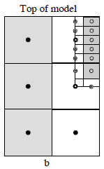 MODFLOW-LGR1 Fig 5 b. 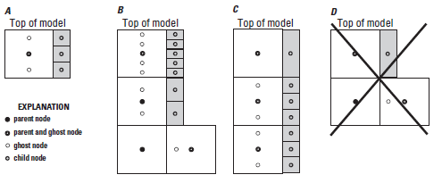 MODFLOW-LGR2 Figure 4. Cross-sectiional schematic of vertical refinement interface of A, a one-layer parent model refined to a three-layer child model; B, a multi-layer parent model where the child refinement varies vertically using both even and odd refinement ratios and terminates at the bottom of the second parent layer; C, a multi-layer parent model where the child refinement varies vertically using a 1:1 refinement ratio in the first layer and a 3:1 refinement ratio in subsequent layers. The refinement extends to the bottom of the parent model; and D, a multi-layer parent model with a single layer child model, which is not possible. |
|


