Using Objects to Specify the Mesh |


Using Objects to Specify the Mesh |
 Scroll to Top of Page
 Print Topic
 Show/Hide Expanders
Using objects to specify a mesh is nearly the same as using objects to specify a grid. However, when generating a mesh, only objects on the top view are used and you are allowed to use point objects as well as lines and polygons. To different methods can be used. The Irregular algorithm used to generate the mesh is modified from the one described by Sarrate and Huerta (2000). Another option is to use the Gmsh program available from http://geuz.org/gmsh/.
To generate the mesh, the user creates one or more objects on the top view of the model. At least one of the objects must be a polygon. The object with the largest area will define the outer boundary of the mesh. Any polygons inside the outer boundary will be treated as holes in the mesh (blue lines, fig. 1). To define polygonal areas within the mesh that will not be holes inside the mesh, two or more polylines that cross each other can be used (red lines, fig. 1). With the Irregular algorithm, edges of elements will lie along the polyline and polygon objects and there will be a node at point objects. The objects can intersect one another. With Gmsh, point objects and the parts of polyline objects that can not be combined to form polygons will be ignored. For each object that will be used to help specify the mesh, the user checks the Use to set mesh element size check box in the Object Properties dialog box and enters a value for the Mesh element size. For profile models, Mesh element size refers to the size of the element in the X direction. The size of the element in the Y direction is the specified size divided by the vertical exaggeration. The user can override the mesh element size for individual vertices in an object by using the Vertex Values dialog box. Any vertex for which the key is set to "Mesh Element Size" will have it's element size set to the value specified. After the objects have been created, the user then selects Mesh|Generate Mesh... or clicks the Generate mesh button  . The Mesh Generation Control Variables dialog box will appear. The user makes sure that the Mesh generation method is set to Irregular and clicks OK to generate the mesh. The user should be aware that there will always be at least one SUTRA node in between any two verticies of an object used to constrain the mesh. The Mesh Information dialog box displays statistics about the mesh.
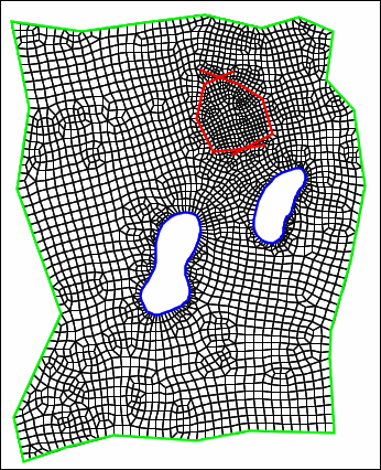 |
Figure. Example of using objects (colored lines) to define where the mesh should be located. The two blue, interior objects define holes in the mesh. The two red interior objects define areas of mesh refinement that are not holes in the mesh. |
The mesh is generated using a domain decomposition approach. The objects used to define the mesh are joined into one or more polygons and nodes are placed along the polygons using the spacing specified by the user. The polygons are then split by selecting two nodes along the polygon and joining them. New nodes are added along the new edge as needed. This is continued until only polygons with four nodes are left. The positions of the nodes are then adjusted and some topological changes are made to improve the mesh quality.
There are seven variables that help control how the mesh is generated. The first variable, Element growth rate, controls the spacing of nodes when new nodes need to be placed along a line and different element spacings have been specified for the two ends of the line. The others control which nodes will be selected as the end points of a line that splits a polygon. When selecting the end points, each potential pair of end points is evaluated according to several criteria to assess which pair of end points is best. The control variables are used to weight each of these criteria in an overall assessment of the the pair of end points. A more detailed discussion of the control variables is presented below.
•Element growth rate: When nodes are added along a line and different element sizes are specified for opposite ends of the line, the spacing between nodes increases from the end with the lower spacing toward the end with the higher spacing. The spacing between nodes is increased by a factor of Element growth rate until the spacing is greater than or equal to the higher spacing or the other end of line is reached. The Element growth rate only has an effect on the final mesh if at least two different Mesh element sizes are specified.
•Splitting angle: Each potential end point forms an angle with the nodes before and after it. Ideally, the new line should split that angle evenly. The splitting angle criterion is a measure of how far from that ideal the new angles will be if a new line is created with a certain pair of end points.
•Line length: The Line length criterion is a measure of the length of the potential new line with shorter lines being preferred.
•Symmetry: The Symmetry criterion is a measure of the difference in area between the two new polygons that would be created with the a new line. Pairs of polygons with equal areas are preferred.
•Concave: If a polygon is concave, splitting at nodes that are at concave angles can result in higher quality meshes so with the Concave criterion, preference is given to nodes at concave angles of the polygon.
•Structure: Ideally, every interior node of a two-dimensional mesh would be part of four elements. Nodes on the edge may have smaller ideal numbers of elements if the angle of the edge of the mesh is sufficiently small. The Structure criterion assigns a value based on the number of polygons of which the node is a part compared to its ideal number.
•Node placement error: When new nodes are placed along a line, it may not always be possible to place them at the exact positions calculated using the Element growth rate. The Node placement error is a measure of the discrepancy between the ideal and actual placement of the new nodes. Setting the Node placement error to a non-zero value only rarely improves mesh quality.
The values Sarrate and Huerta (2000) suggested values for control variables are used as defaults in ModelMuse. For the other control variables (Element growth rate and Concave), numerical experiments were performed to identify appropriate default values. However, no single set of control values was ideal for every tested model. If the mesh generated with the default values is not satisfactory, the user may try varying any of the control variables. Sometimes a small change in a control variable results in a radically different final mesh.