MT3D-USGS Stream and Lake Transport |
MT3D-USGS Stream and Lake Transport |
This illustrates the gwt example from the MT3D-USGS model. The model is described starting on page 56 of the MT3D-USGS documentation (Bedekar and others, 2016). The model simulates solute transport with transfer of solutes among lakes, streams, and groundwater. This model was based on one presented in the documentation of the SFR package in Prudic and others (2004) starting on page 24.

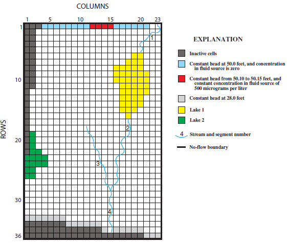
Finite-difference model grid of layer 1, boundary conditions, and locations of lakes and streams (from Prudic and others, 2004).
In general, flow is from North to South due to constant head boundaries. The model has four stream segments and two lakes. Two of the stream segments (segments 1 and 3) have small amounts of solute in them but the main source of solute is from a few of the constant head boundary cells on the Northern edge of the model with concentrations of 500 mg/l.
Because the main interest in this model is the solute transport portion, we will import the existing flow model and then show how to add the solute transport portion.