MODFLOW 6 Subsidence Example |
MODFLOW 6 Subsidence Example |
This example illustrates how to use the Skeletal Storage, Compaction, and Subsidence (CSUB) Package. It reproduces example 4 from csubexamples.pdf distributed with MODFLOW 6 version 6.1. There is a more complete description of the model in csubexamples.pdf. The model is loosely based on an example from Leake and Galloway (2007).
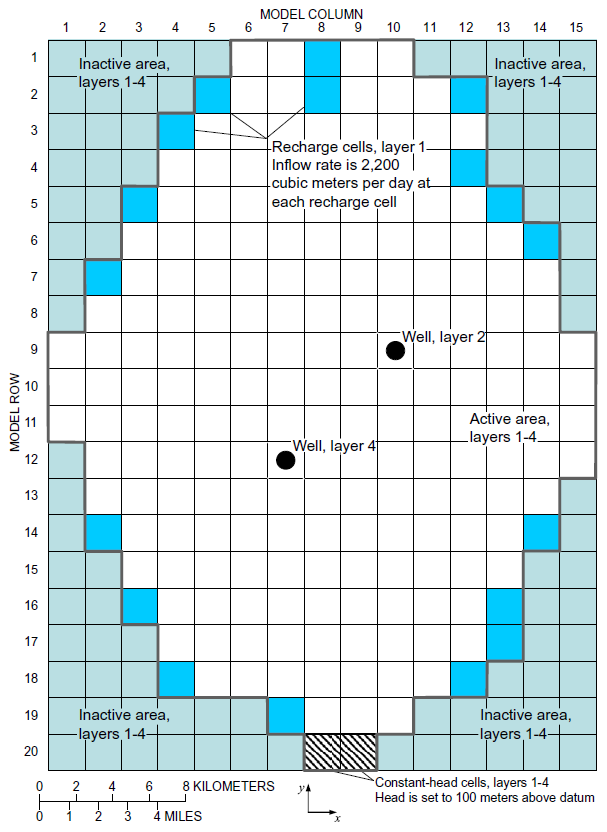
The model has 15 columns, 20 rows, and 4 layers.

Plan view of model domain showing active and inactive areas, and locations of recharge cells, constant-head cells, and wells.(from Leake and Galloway, 2007)
Properties and conditions represented in the CSUB Package:
1. Interbed systems are present in all four layers.
2. Specific gravity of moist sediments is 1.7 and of saturated sediments is 2.0.
3. Thicknesses of compressible sediments in systems 1–4 is 45, 70, 50, and 90 meters, respectively.
4. Recompression index for all systems of interbeds is 0.01.
5. Compression index for all systems of interbeds is 0.25.
6. Void ratio for all systems of interbeds is 0.82.
7. Starting preconsolidation stress is 15 meters above starting effective stress for all active cells.
Properties and conditions represented in the Node-Property Flow Package:
8. Horizontal hydraulic conductivity for layers 1–4 is 4, 4, 0.01, and 4 meters per day, respectively.
9. Vertical hydraulic conductivity for layers 1–4 is 0.4, 0.4, 0.01, and 0.4 meters per day, respectively
Properties and conditions represented in the Storage Package:
10. Specific yield for layer 1 is 0.3.

Generalized section along model row 9 showing types of fine-grained sediments, model layering, and properties and conditions used in the example simulation. Aquifer-system properties and other conditions are listed in figure 5. For simplicity, all material and hydraulic properties and conditions are constant within each model layer or interbed system. (from Leake and Galloway, 2007)
In the model, there are three geologic units but the upper geologic unit is divided into two layers. The model has a top elevation of 150 meters and layer bottom elevations of 50, -100, -150, and -350 meters for layers 1, 2, 3, and 4, respectively. The top layer is unconfined. The cells are square with an edge length of 2000 meters. There are 15 rows and 20 columns. Recharge is from rivers that flow into the valley from either side. There are two wells. One is in layer 2 and the other is in layer 4. The third layer is composed entirely of fine-grained compressible sediments. The other layers have interbeds of fine-grained compressible sediments.