CSUB Example: Specified-Head Boundary |
CSUB Example: Specified-Head Boundary |
The model has a specified-head boundary with a value of 100 extending through all four layers in the southernmost row of the model.
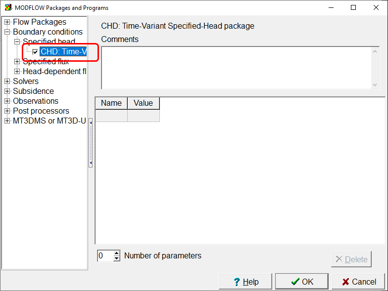
The first thing to do is to activate the CHD package. Select Model|MODFLOW Packages and Programs and check the check box for the CHD package. Click OK to close the dialog box.

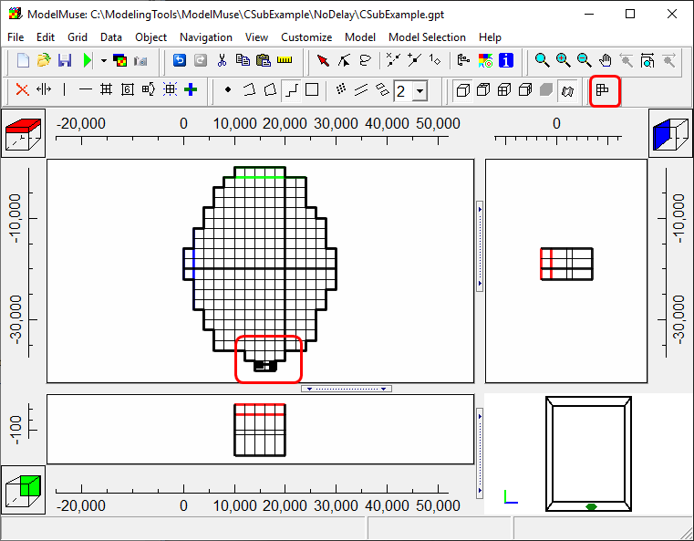
The specified-head boundary is only in the active cells, of course. To make it easier to recognize which cells are active, select View|Show or Hide 2D Grid|Show Active. This option is also available through a button on the main window  . Next, create a polyline or straight-line object in the active cells in the last row of the model.

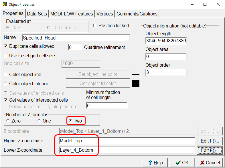
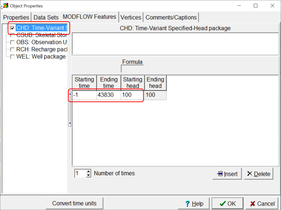
In the Object Properties dialog box, set the formulas for the Z coordinates so that all four layers will be intersected by the object. Then go to the MODFLOW Features tab and set the times and values for the CHD package. Because the CHD boundary will remain the same through all three stress periods, you can specify the beginning time as the beginning of the first stress period and the ending time as the end of the third stress period. Click OK to close the Object Properties dialog box. You can color the grid with the CHD boundary to make sure it is being assigned properly. You can use the Selection Cube on the front view to change the selected row to the southernmost row of the model so that you can see the specified heads on all four layers on the front view of the model.

