Cross Sectional Model: Specifying the Grid |


Cross Sectional Model: Specifying the Grid |
 Scroll to Top of Page
 Print Topic
 Show/Hide Expanders
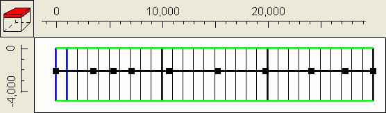
Objects can only be used to specify the elevations of the layer boundaries if they are 2D objects on the top view of the model. We will use a line object to specify the elevations. Click on the "create straight-line object" button  and draw a line across the top view of the model.It will be used to specify the elevations of the model boundaries as a series of straight line segments. Make a separate vertex at each place where you might want to have a change in slope of a layer boundary. Double-click when you are done with the object and then click OK in the Object Properties dialog box.
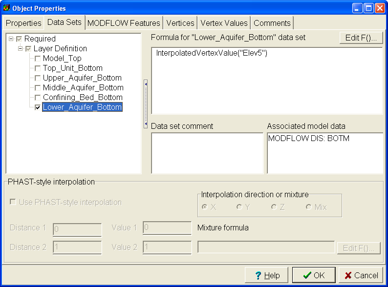
The next steps will associate values with several of the vertices. Then we will interpolate along the line to specify the elevation of one of the layer boundaries. Click the "Edit vertex value" button  and double-click on the vertex on the far right. In the Vertex values dialog box, set the "Key" to Elev5 and the value to -5 which is the elevation of the bottom of the bottom layer at this position. Click OK to close the Vertex values dialog box. Next double-click on the vertex on the far left and enter a value of 55 for Elev5. Now select "Object|Select Objects" and double click on the object to open it in the Object Properties dialog box. On the Properties tab, change the number of Z formulas to zero. Then switch to the "Data Sets" tab, expand "Required|Layer Definition" and check the check box for the elevation of the bottom unit. Then set the formula to InterpolatedVertexValue("Elev5"). Click OK to close the dialog box.
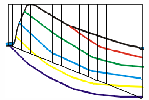
The front view of the model should now look similar to the figure below.
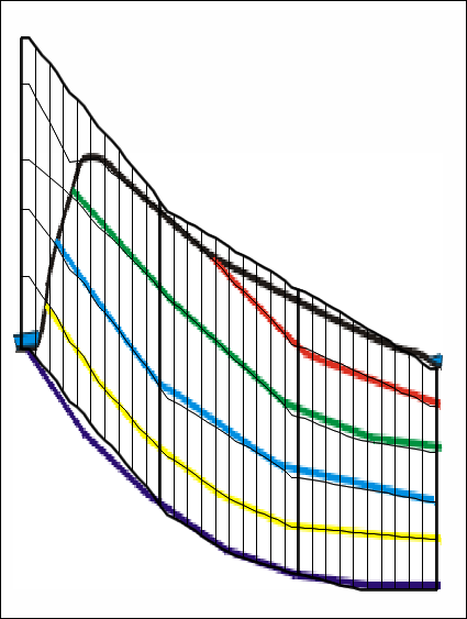
Try moving the mouse over the front view of the model while looking at the Status Bar. Read the Z elevation from the status bar and use it to set the value of Elev5 for some of the other vertices of the object. Edit them until you get match to the background image that you think is good enough. Repeat the process to define the elevations of the other layer boundaries. For the parts of the geologic units that have been eroded away, extrapolate where the boundaries would have been if those geologic units were still present. When you are done, you might have something similar to the figure below. (A completed version of this model is installed in the C:\Users\Public\Documents\ModelMuse Examples\examples\MODFLOW directory. If you wish, you can look at the values assigned to the various vertices in the example.)