The model grid is 135 m long and 50 m wide. To create the grid, create a rectangle object with those dimensions and use it to assign the grid size. Put the upper left corner at (0,50) and the lower right corner at (135,0). After the object is created, edit the vertices to be at the following coordinates. You can copy this block of values from this document and paste it into the Vertices tab of the Object Properties dialog box.
0, 50
135, 50
135, 0
0, 0
0, 50
On the Properties tab, check the "Use to set grid size" check box and set the grid size to 2.5. After clicking OK to close the Object Properties dialog box, select "Grid|Generate Grid." In the Generate Grid dialog box, click OK to generate the grid.
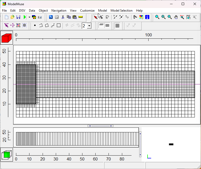
Next we will create a refined area on the left edge where the well will be. The refined area should be rectangular and extend from (0,40) to (15,10). This extends in the y direction somewhat beyond where the well will be on the left edge. On the properties tab, set the Quadtree refinement to 2. The coordinates of the object should be the following.
0, 40
15, 40
15, 10
0, 10
0, 40
Now we will create another refined area encompassing the middle zone where most of the flow will take place. It should have a Quadtree refinement of 1 and extend from (15,35) to (135,15). The coordinates of the object should be the following.
15, 35
135, 35
135, 15
15, 15
15, 35
Now select "Grid|Switch to DISV." You grid should appear similar to the following image.

DISV Grid in the ATES model.