


|
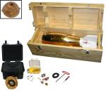
P-6 Sampler, with Case | |
|---|---|
HIF/FISP Part # 4102010 | |
|
*Call the HIF at (800) 382-0634 for final pricing and
ordering.
The sampler head contains an electrically actuated, two-position valve and several passageways that convey the sample and air. The body has a hollow interior, which serves as a compression chamber that forces air through the head to the sample container to equalize pressure in the sampler as it transits through the water. Pressure equalization prevents a hydrostatically induced in-rush of sample as the valve is opened. The sampler head is attached to the body by a hinge and held closed by a latch. The head pivots on the hinge to open and provide access to the sample container (figure 2). When the head is closed the sample container is sealed against a gasket mounted in the rear of the head. A bottle spring exerts force against the base of the sample container to maintain a seal between the bottle gasket and the sample container. The valve is actuated by a simple direct current tubular linear solenoid and return spring that is commercially available. The operation of the valve causes the sampler to operate in the same way as the other FISP point-integrating samplers; however its design is quite different from the hand-lapped tapered valve used in previous samplers. The valve has two flat faces approximately 120 degrees apart and rotates approximately 30 degrees about the intersection of the two faces. It has foam material cemented to the flat metal faces that create a leak-proof seal of the passage ways. With no electrical power applied, the valve is in the pressure-equalizing position. As the sampler is lowered through the water, hydrostatic pressure forces water through the holes in the bottom of the sampler into the compression chamber compressing the air in the chamber. The increased pressure is transmitted through passageway that connects the pressure chamber in the body through the head to the sample container. The pressure in the sample container is balanced with the ambient pressure near the nozzle. When power is applied, the solenoid rotates the valve to the sampling position. The connection through the head to the compression chamber closes and the passage through the nozzle to the sample container opens. The sample enters the sample container without surging. Air displaced by the sample is expelled through a passage from the sample container to the exhaust vent on the side of the head. Sampling terminates when power is removed and the valve returns to the equalizing position. The sampler must be suspended on a sheathed single-conductor cable. The cable should have a diameter of 1/8 inch (3.2 mm) to minimize drag. The resistance in the cable should not exceed 100 ohms per 1000 feet (305 m). The cable sheath (exterior load-bearing strands) is connected to a special clamp which is pinned to the top end of the hangar bar. The insulated conductor, located in the center of the cable, is connected to one of the solenoid (electrical) lead routed through the upper vent of the sampler head. The remaining solenoid lead is connected to the sheath of the coaxial suspension cable or directly to the clamp. This provides proper grounding of the electrical circuit and completes connections at the sampler end of the cable. When power is applied at the reel, current will flow from the supply, through the center conductor of the cable and through the solenoid. Current will return through the grounding jumper wire, cable clamp, the cable sheath, and the reel frame. USGS B and E reels are best suited for deploying the sampler. The power supply must be direct current (DC) of at least 24 volts which, at remote sites, is most conveniently obtained from dry or wet cell batteries. The supply voltage is set by the required current and the total resistance in the cable and solenoid. For a 100-foot cable with a resistance of 100 ohms/1000 feet, the cable resistance should be 10 ohms. The US P-6 uses a Ledex® Tubular Linear Solenoid (Part No. 195202-231) which has a resistance of 9.56 ohms and requires 24 volts to actuate the valve. With this cable, the voltage must be no less than 24 volts. To provide a margin of reliability and compensate for battery discharge, 36-volt DC may be used. The sampler uses a 3/16 in internal diameter nozzle and can be used in stream velocities ranging from 1.5 to 10 ft/sec. It can be used to a depth of 160 ft with a 1-liter sample container. Each unit includes shipping box, 2 nozzles, 2 gaskets, and a hanger bar. HIF Repairable.Where and how the sampler is deployed in the field is as important as the fundamental design of the sampler. Additional information about how to properly use this sampler can be found in the following references: Associated Components
4107020 BOTTLES, 1-LITER, PLASTIC | |

![]() U.S. Department of the Interior |
U.S. Geological Survey
U.S. Department of the Interior |
U.S. Geological Survey
URL: http://water.usgs.gov/fisp/products/4102010.html
Page Contact Information: USGS Office of Surface Water
Page Last Modified: Friday, 21-Dec-2018 10:31:23 EST
 The sampler consists of three major assemblies: the head, body, and tail. The sampler head and body is cast bronze and the tail section is constructed of high density polyethylene. The sampler weighs 100 pounds (45.4 kg) and is 29.5 inches (0.75 m) long. The sampler is streamlined and has tail fins to orient it so the intake nozzle located in the head is directed into the approaching flow. The intake nozzle has an internal diameter of 3/16 inch (4.76 mm); and this is the only nozzle available for the US P-6. The sampler is designed to use various size bottles as a sample container. The bottle cavity has a diameter of 3.95 inches (10 cm), length of 8 inches (20 cm), and an adjustable, removable bottle spring. When the sampler head is closed the mouth of the sample container is sealed against a gasket mounted in the rear of the head. Typical 1-liter sample bottles will fit the sample container, and 1-pint bottles can be accommodated using a sample bottle sleeve.