FOR EACH SIMULATION
|
Data Set 0
|
[#Text]
Item 0 is optional—“#” must be in column 1. Item 0 can be repeated multiple times.
Text—is a character variable (199 characters) that starts in column 2. Any characters can be included in Text. The “#” character must be in column 1. Except for the name file, lines beginning with # are restricted to these first lines of the file. Text is printed when the file is read.
|
|
Data Set 1
|
NLAY NROW NCOL NPER ITMUNI LENUNI
NLAY—is the number of layers in the model grid. In MODFLOW-2000, the maximum number of layers is 999. In MODFLOW-2005, there is no fixed limit to the number of layers.
|
NROW—is the number of rows in the model grid.
|
NCOL—is the number of columns in the model grid.
|
NPER—is the number of stress periods in the simulation.
|
ITMUNI—indicates the time unit of model data, which must be consistent for all data values that involve time except for certain variables in the DAFLOW package. For example, if years is the chosen time unit, stress-period length, time-step length, transmissivity, and so on, must all be expressed using years for their time units. Note that the program will still run even if “undefined” time units are specified because the fundamental equations used in MODFLOW do not require that the time unit be identified. But be sure to use consistent units for all input data even when ITMUNI indicates an undefined time unit. When the time unit is defined, MODFLOW uses it to print a table of elapsed simulation time:
|
LENUNI—indicates the length unit of model data, which must be consistent for all data values that involve length except for certain variables in the DAFLOW package. For example, if feet is the chosen length unit, grid spacing, head, hydraulic conductivity, water volumes, and so forth, must all be expressed using feet for their length units. Note that the program will still run even if “undefined” length units are specified because the fundamental equations used in MODFLOW do not require that the length unit be identified. But be sure to use consistent units for all input data even when LENUNI indicates an undefined length unit:
If using the DAFLOW package, make LENUNI consistent with the value specified for IENG.
|
|
|
Data Set 2
|
LAYCBD—is a flag, with one value for each model layer, that indicates whether or not a layer has a Quasi-3D confining bed below it. 0 indicates no confining bed, and not zero indicates a confining bed. LAYCBD for the bottom layer must be 0.
|
|
Data Set 3
|
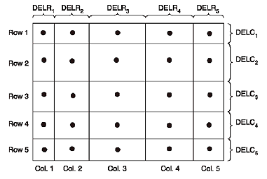
DELR(NCOL) - U1DREL
DELR—is the cell width along rows. Read one value for each of the NCOL columns. This is a multi-value one-dimensional variable with one value for each column.
 Finite difference grid illustrating DELR and DELC. |
|
Data Set 4
|
DELC(NROW) - U1DREL
DELC—is the cell width along columns. Read one value for each of the NROW rows. This is a multi-value one-dimensional variable with one value for each row.
 Finite difference grid illustrating DELR and DELC. |
|
Data Set 5
|
Top(NCOL,NROW) - U2DREL
Top—is the top elevation of layer 1. For the common situation in which the top layer represents a water-table aquifer, it may be reasonable to set Top equal to land-surface elevation.
|
|
Data Set 6
|
BOTM(NCOL,NROW) - U2DREL
Item 6 is repeated for each model layer and Quasi-3D confining bed in the grid. These layer variables are read in sequence going down from the top of the system. Thus, the number of BOTM arrays must be NLAY plus the number of Quasi-3D confining beds.
BOTM—is the bottom elevation of a model layer or a Quasi-3d confining bed.
|
|
FOR EACH STRESS PERIOD
|
Data Set 7
|
PERLEN NSTP TSMULT Ss/tr [STARTTIME StartingYear]
PERLEN—is the length of a stress period.
|
NSTP—is the number of time steps in a stress period.
|
TSMULT—is the multiplier for the length of successive time steps. The length of a time step is calculated by multiplying the length of the previous time step by TSMULT. The length of the first time step, Dt1, is related to PERLEN, NSTP, and TSMULT by the relation

|
Ss/tr—is a character variable that indicates if the stress period is transient or steady state. The only allowed options are “SS” and “TR”, but these are case insensitive.
|
|
|


