|
RMA: Wells |
|
RMA: Wells |
The final step is to define the well boundaries. The wells will include the two actual wells in the south as well as the disposal pond. Recall that the disposal pond is to the north of the two interior areas underlain by impermeable bedrock and that the two pumping wells are south of them.
First, the Well package must be activated. Select Model|MODFLOW Packages and Programs. Expand Boundary conditions|Specified flux and check the check box next to WEL. Click OK to close the dialog box.
Next select the object that represents the disposal pond. Double-click on it to open the Object Properties dialog box. Change the name of the object to "Disposal Pond." Make sure that Set values of intersected cells is checked. Change Number of Z formulas to One and check that the formula for Z-coordinate is set to "(Model_Top + Aquifer_Bottom) / 2."
On the MODFLOW Features tab, check the check box for the WEL package, change the Number of times to 1 and the Pumping rate interpretation to Total. Then change the Starting time and Ending time to 0 and 631152000 respectively. Set the Total Pumping rate to 0.025. (The positive sign indicates that flow is into the aquifer.) This flux will be divided over several cells. The sum of the pumping rate in all the cells will add up to 0.025 because the Pumping rate interpretation has been set to Total. Click OK to close the dialog box. Color the grid with the well pumping rate and see how many cells are well cells due to the disposal pond. If desired, the user can select Data|Show Grid or Mesh Values... and confirm that the total pumping rate adds up to 0.025.
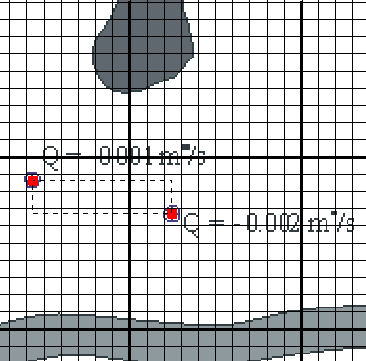
For the two pumping wells, it is more convenient to show the background image and hide all the objects. If the background image is not visible, select Edit|Show or Hide Image Then click the Show or hide objects button  . In the Show or Hide Objects dialog box, uncheck the checkbox for All Objects. On the background image, find the two wells (in red in the figure 115). Click the Create point object button
  and click at one of the wells (fig. 115). In the Object Properties dialog box, change the name to something appropriate. On the MODFLOW Features tab, check the check box for the WEL package and change the Number of times to 1. Set the Pumping rate interpretation to Direct. Change the Starting time and Ending time to 0 and 631152000 respectively. Enter the correct Pumping rate for the well (-0.001 for the western well, - 0.002 for the eastern well). Be sure that the pumping rates are negative indicating that water is being pumped out of the aquifer. Repeat for the other well.

Figure 115. Two objects in red used to simulate wells.