MT3D-USGS Contaminant Treatment System Example |
MT3D-USGS Contaminant Treatment System Example |
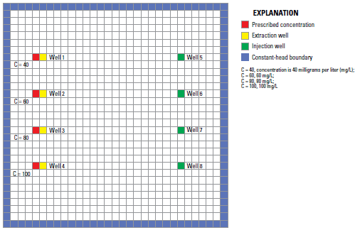
This example illustrates how to reproduce the CTS1 example that comes with MT3D-USGS. The example is described beginning on page 46 of the MT3D-USGS documentation (Bedekar and others, 2016). Briefly, the model has 1 layer and 31 rows and columns. The cells are 900 feet long and wide and 20 feet thick. There are 4 extraction wells on the left half of the model and 4 injection wells on the right half of the model. Four specified concentration boundaries are located in the cells to the left of the extraction wells. The two stress periods are both transient and have lengths of 912.5 and 2737.5 days respectively (= 2.5 and 7.5 years).

CTS model configuration including specified concentrations from Bedekar and others, 2016.
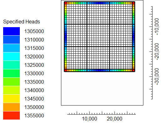
The specified heads vary along the edges of the models with the highest heads at the corners of the grid.
 Specified heads |
Both the extraction and injection rates increase between the first and second stress periods. The specified concentrations decreases by 10 between the first and second stress periods. Two contaminant treatment systems are included in the model, In each system the contaminated, extracted water from the extraction wells is treated and reinjected in the injection wells but both the extraction and injection wells included in each treatment system differ between stress periods 1 and 2.