Next we'll define a multi-aquifer well.
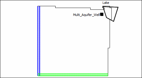
1.Click the "Create point object" button  . Then click on the top view of the model near but not in the lake. The idea is to create it in the area where there are vertical flow-through cells to demonstrate that the vertical flow-through cells don't create a problem for the multi-aquifer well.

Location of Multi-Aquifer Well
2.On the Properties tab of the Object Properties dialog box, set the number of Z formulas to zero. (The vertical location of the multi-aquifer well is defined by it's well screen which we'll get to later.
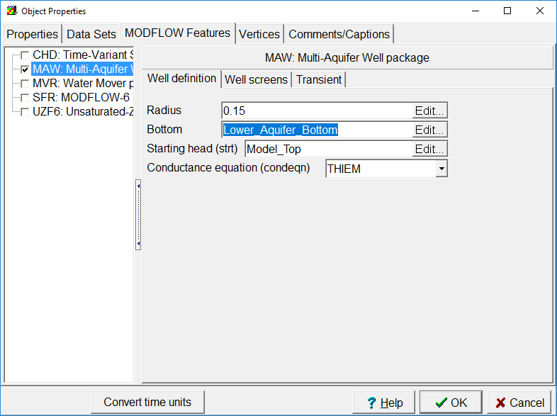
3.On the MODFLOW Features tab, check the checkbox for the Multi-Aquifer well package. On the Well definition tab for the multi-aquifer well, set the radius to "0.15" m, the Bottom to "Lower_Aquifer_Bottom," the starting head to "Model_Top," and the Conductance equation to "THIEM."

Well definition tab.
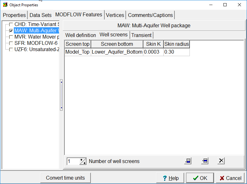
4.Switch to the Well Screens tab and set the Screen top to Model_Top, the Screen bottom to Lower_Aquifer_Bottom, the Skin K to 0.0003, and the Skin radius to 0.30 m.

Well screens tab
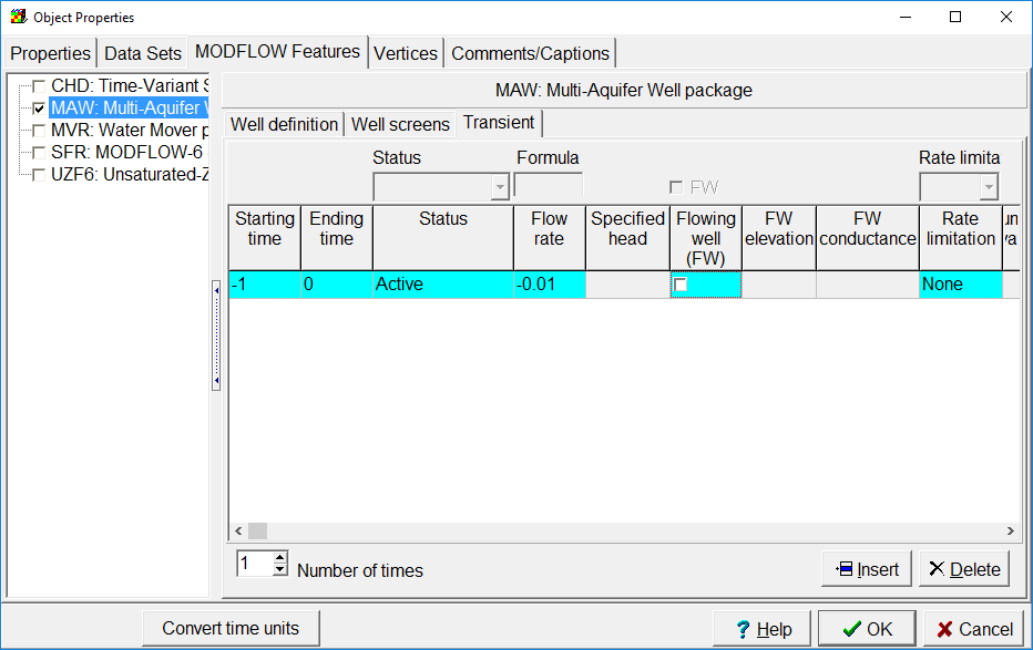
5.On the Transient tab, set the starting and ending time to -1 and 0. Set the Status to Active, the Flow rate to -0.01, and the Rate limitation to None.

Transient tab for Multi-aquifer well
6.Click OK to close the dialog box.