Example Model |


Example Model |
 Scroll to Top of Page
 Print Topic
 Show/Hide Expanders
Please note that this example works with MODFLOW-2005 but for it to work with MODFLOW 6, some changes need to be made to the model.
The goals of this example are to:
1.Introduce the ModelMuse main window.
2.Introduce objects.
3.Introduce some of the important ModelMuse dialog boxes.
4.Illustrate how objects can be used to define non-uniform layer boundaries in MODFLOW models.
5.Introduce how to work with MODFLOW parameters in ModelMuse.
6.Introduce how to select MODFLOW packages in ModelMuse.
7.Introduce methods for importing data and background images.
8.Introduce methods for viewing model results.
9.Introduce a method for saving an image of the model.
The model in this example has already been created and is used to illustrate a variety of features in ModelMuse. Some of the features that the model illustrates are (1) spatially varying layer elevations, (2) the use of parameters, multiplier arrays, and zone arrays to define aquifer properties, (3) defining boundary conditions, (4) importing data and images, (5) running the model, and (6) viewing model results. The model has ten rows, ten columns, and nine layers. The model has several specified head boundaries and a well. The spatial distribution of the hydraulic conductivity in the Layer Property Flow (LPF) package is defined using a combination of parameters, multiplier arrays, and zone arrays.
To open the example model, start ModelMuse (by double clicking on ModelMuse.exe) and select "Open an existing model." Go to the ModelMuse Examples directory. It will most likely be in "C:\Users\Public\Documents\ModelMuse Examples\examples\MODFLOW."
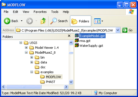
Select ExampleModel.gpt (in the "C:\Users\Public\Documents\ModelMuse Examples\examples\MODFLOW" folder) and the model will open. It should look similar to figure 66.
The ModelMuse main window shows four views of the model. The view on the upper left is a view from the top. The view on the upper right is a view from the right side. The view on the lower left is a view from the front. The view on the lower right is a three-dimensional (3-D) view of the model. The user can edit the model in the top, front, and side views. The model can be viewed but not edited in the 3-D view.
Three point objects (the small squares) are visible on the top view of the model. One of the squares is black, indicating that it is the selected object. If the Select objects button  in the toolbar is depressed, it is possible to double click on an object to display the Object Properties dialog box. The Object Properties dialog box is how the user defines what role each object plays in the model. Another important dialog box is the Data Sets dialog box. Data sets define things such as the hydraulic conductivity of the aquifers and the elevations of the layer boundaries. Some data sets are created by ModelMuse, but the user can create additional data sets for other purposes.
 |
Figure 66. Initial appearance of ExampleModel.gpt. |