|
Discretization Tab |
|
Discretization Tab |
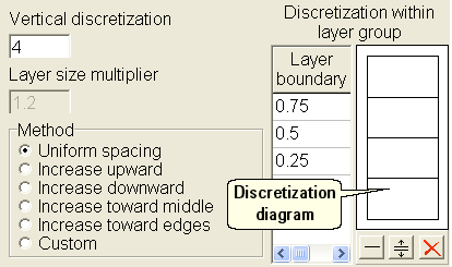
The Discretization tab is on the MODFLOW Layer Groups dialog box.
The Vertical discretization specifies how many layers will be present in each layer group. Typically, each aquifer in the model will be represented by a single layer.
If the Vertical discretization is greater than one and the method is neither Uniform spacing nor Custom, the Layer size multiplier specifies the ratio of the thickness of a layer in a layer group to its neighbors.
The Method specifies how the thickness of layers within a layer group will be determined. Typically, a uniform spacing is used.
•Uniform spacing - all the layers in the layer group are the same thickness.
•Increase upward - the layers increase in thickness toward the top of the layer group at a rate specified by Layer size multiplier.
•Increase downward - the layers increase in thickness toward the bottom of the layer group at a rate specified by Layer size multiplier.
•Increase toward middle - the layers increase in thickness toward the middle of the layer group at a rate specified by Layer size multiplier.
•Increase toward edges - the layers increase in thickness toward the outside edges of the layer group at a rate specified by Layer size multiplier.
•Custom - the thickness of each layer within the layer group is specified individually through the Discretization within layer group table.
The Discretization within layer group table is used to specify the positions of the boundaries between layers in a layer group. The numbers represent the fractional difference from the bottom to the top of the aquifer group of the position of the boundaries between layers. Data can be entered directly in the table in the Method is Custom or the can be specified graphically using the Discretization diagram as illustrated in figure 34 below. To add a new layer boundary graphically, click the Insert grid line  button and then click in the Discretization diagram where the layer boundary should appear. To move an existing layer boundary graphically, click the Move grid line
  button and then drag the layer boundary to a new position. To delete an existing layer boundary graphically, click the Delete grid line
  button and then click on an existing layer boundary in the Discretization diagram.

Figure 34. Discretization tab of the MODFLOW Layer Groups dialog box.