
Prepared in cooperation with the Nebraska Platte River Cooperative Hydrology Study Group
Fact Sheet 115—03
January 2004
Figure 1. Location of study area, including major rivers, and canals.
Figure 2. Typical seismic reflection ray paths (from Haeni, 1986, p. 25).
Figure 3. Boom launching tow vehicle.
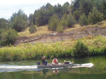
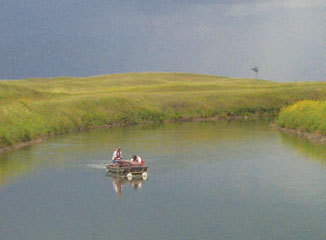
Figure 4. Tow vehicle being pushed by motorboat.
Figure 5. Tow vehicle being pulled by passenger vehicles.
Figure 6. Continuous bedrock reflectors well-defined, continuous, and corre...
Figure 7. Non-continuous bedrock reflectors well-defined, non-continuous, a...
Figure 8. Multiples multiple reflectors that obscure bedrock reflectors and...
Figure 9. Poor sub-bottom penetration penetration inadequate to identify be...
Figure 10. No sub-bottom penetration Tri-County Canal at Midway Lakes near ...
In central and western Nebraska, the Platte River and its underlying alluvial aquifer are vital sources of water for irrigation, power production, and recreation. Scientists and water managers need accurate knowledge of the saturated thickness, or thickness between the water table and less permeable underlying bedrock, of the alluvial aquifer to better understand ground-water movement and interactions between ground water and surface water (COHYST Technical Committee, 2000). Typically geologic logs and bedrock outcrops are used to map the depth of the bedrock surface. Although geophysical methods have been used to investigate shallow geologic deposits in central and western Nebraska (Ellis and Hiergesell, 1985), no investigations had been conducted using water-borne continuous seismic-reflection profiling (CSP) techniques. In 2001, the U.S. Geological Survey (USGS) and the Nebraska Platte River Cooperative Hydrology Study (COHYST) engaged in a cooperative pilot study to determine if CSP could be used to determine depth to bedrock and the general characteristics of alluvial sediments in the Platte River Basin (fig. 1). This report: (1) describes the methodology used to obtain the CSP records, (2) provides examples of data obtained from CSP surveys, and (3) evaluates the usefulness of the results obtained with the CSP technique.
Figure 1. Location of study area, including major rivers, and canals.
The Platte River is a substantial source of water for western and central Nebraska. Diversions along the Platte River deliver water to irrigation and power canals, which usually are unlined channels excavated in alluvial deposits in the Platte River Valley. Surficial geologic maps in the alluvial deposits are often based on sparse distributions of geologic logs. In addition to the lithological data obtained from geologic logs, surface geophysical techniques provide scientists with a noninvasive, efficient method of obtaining information about geologic deposits. CSP is a water-borne surface geophysical technique that can be used in a variety of marine, estuarine, riverine, and lacustrine settings to define the geologic framework of aquifer systems, locate hydrologic boundaries, and in some places, to interpret the lithologic character of the aquifer and confining beds (Haeni, 1986).
In August 2001, approximately 90 miles of CSP data were collected along six irrigation and power canals in two regions of the Platte River Basin in central and western Nebraska. These two regions included the North Platte, South Platte, and Platte Rivers and were differentiated by the geologic formations underlying the principal aquifer, and by the periods of canal operation in each region–seasonal or perennial.
For this report, the Western Region is defined as the region that occupies the North Platte Natural Resources District (NRD) in the North Platte River Basin Valley upstream from Lake McConaughy. Water-bearing sediments in this region are part of the High Plains aquifer. In the Western Region, siltstone and clay deposits of the Tertiary-age Brule Formation bedrock underlie the High Plains aquifer, which generally consists of Quaternary-age alluvial and eolian sand and gravel in this area. The depth to bedrock in this region varies from less than 10 feet to more than 200 feet. Segments of Interstate Canal and Tri-State Canal were investigated. These canals provide surface water for irrigation and are a substantial ground-water recharge source (Verstraeten and others, 2001). Diversions into these unlined canals typically occur from May to September. During October to April, the empty canals are intermittently repaired with machinery that may cause compaction of the canal bottom sediments.
For this report, the Central Region is in the South Platte and the Platte River Basin Valleys downstream of Lake McConaughy and occupies parts of the Central Platte, Twin Platte, and Tri-Basin NRDs. The High Plains aquifer also is the principal aquifer in the Central Region and is composed of Quaternary-age alluvial sediments overlying consolidated to semi-consolidated sand and gravel deposits of the Tertiary-age Ogallala Formation. Canals in the Central Region are in areas containing loess and alluvial sediments underlain by more consolidated Ogallala Formation bedrock. Sections of Sutherland Canal, Tri-County Canal, Phelps County Canal, and Kearney Canal were investigated. Water generally is supplied to the canals year-round for power production and is used for seasonal irrigation, with the exception of the Kearney Canal, which is only used for irrigation during May through September.
In August 2001, the USGS with assistance of COHYST personnel collected about 90 miles of CSP data in canals in the Platte River Basin. The depth of water in the Platte River and its tributaries, in most places, was less than or near the minimum depth of about 4 feet required for the operation of CSP. Therefore, data were collected on segments of canals in the North Platte, South Platte, and Platte River Basins that varied in depth from about 5 to 15 feet. The ease of deployment and operation allowed data collection in several areas where depth to bedrock was expected to be irregular or poorly understood. Some canal segments were inaccessible by boat or land vehicle and were not surveyed.
Swept-frequency CSP is a towed, digital, frequency-modulated seismic reflectivity technique capable of producing high-resolution images of sediments underlying water bodies. Swept-frequency CSP was chosen because it is a wideband acoustic source that transmits computer-generated pulses that sweep over a frequency range of 200 to 30,000 Hertz (Hz). Such wide bandwidth pulses ensure that sediment layers as close as 5 centimeters apart can be resolved with optimum field conditions (LeBlanc and others, 1995). Swept-frequency CSP also was chosen because separate transmit and receive arrays mounted in a single tow vehicle allow for data to be collected in areas containing surface obstructions and areas of navigational difficulty.
The CSP system generates a linear swept, frequency-modulated acoustic signal that propagates into the water column and subsurface from a tow vehicle suspended just below the water surface. Acoustic energy is an elastic wave that travels through a homogeneous elastic medium with a series of compressions and refractions. The velocity at which the signal travels in solids or liquids is proportional to the elastic properties and inversely proportional to the density of the transmitting medium. As the signal propagates, its energy is lost by divergence, reflection, scattering, and absorption (Haeni, 1986). A proportion of the acoustic energy from this signal is absorbed by the water column and reflected by the bottom material, and a proportion continues to propagate through the bottom materials and is reflected from subsurface interfaces of subsurface sediments (fig. 2). The water bottom and subsurface sediments often behave as acoustic interfaces that reflect an outgoing signal back to a receiving array. Separate transmitting (transducer) and receiving (hydrophone) arrays mounted in the tow vehicle are used to allow for simultaneous transmission and reception of the acoustic signal. The depth to geologic strata (subsurface reflector) is determined by the two-way travel time (the time it takes for the signal to travel from the transmitter to the reflective layer and back to the receiver) and the velocity of sound in water and subsurface. The signal at the receiver array is digitized with a 16-bit analog-to-digital converter at a sampling rate of 25 kHz (kilohertz). The CSP system is designed for profiling at speeds up to 8.6 miles per hour. The benefits of using a swept-frequency source in place of low frequency sources used in reflective-seismic surveying is the combination of greater penetration because of the lower frequencies and increased resolution because of the higher frequencies.
Figure 2. Typical seismic reflection ray paths (from Haeni, 1986, p. 25).
A topside unit running acquisition software written by Trition Elics, International1, controlled the tow vehicle, manufactured by EdgeTech. A signal sweeping from 2 to 10 kHz was used at a rate of 4 times per second and was chosen to maximize the depth of penetration and a record length of 250 milliseconds (about 650 feet of depth) was chosen to accommodate the varying depth of the bedrock. A differential Global Positioning System manufactured by Trimble with 1-meter accuracy was used to locate the source and receiver locations of the swept-frequency CSP data.
The CSP system was deployed in two ways during this study. A flatbed trailer equipped with a 20-foot boom was used to deploy the 450-pound (192 kg) tow vehicle along the canal banks (fig. 3). In wide canals, the tow vehicle generally was fixed to the bow of a motorboat and pushed downstream along the centerline of the canal (fig. 4). In some locations, low bridge clearance, high water velocity, and steep canal banks prevented the use of a motorboat to propel the tow vehicle. In these locations, two passenger vehicles, traveling on opposing canal banks at similar speeds, pulled the tow vehicle with towropes in the upstream direction along the centerline of the canal (fig. 5). The tow vehicle was towed at approximately 1 to 3 miles per hour. Raw data collected from the CSP equipment were printed and stored on digital media. Triton Elics software was used to apply filters and other processing techniques to enhance the visual appearance of the seismic signal.
Figure 3. Boom launching tow vehicle.
Figure 4. Tow vehicle being pushed by motorboat.
Figure 5. Tow vehicle being pulled by passenger vehicles.
A preliminary review of the 90 miles of survey data was made to evaluate the data in each region and to determine if CSP could be used to quantify accurately the depth of the bedrock surface underlying the alluvial aquifer. A subset of 23 miles of the data, including 6.8 miles of Tri-State Canal, 3.5 miles of Sutherland Canal, 10.5 miles of Tri-County Canal, and 1.9 miles of Tailrace near North Platte, was selected for interpretation based on priorities identified by COHYST staff. These data were then classified into five categories:
1. Continuous bedrock reflectors—well-defined, continuous, and with a nearby geologic log; for example, Sutherland Canal near Lake McConaughy, Nebraska (fig. 6).
Data that were classified as indicating continuous bedrock reflectors or non-continuous bedrock reflectors were considered to be successful in identifying the consolidated bedrock underlying the canals. The depth to bedrock (D) was calculated for these data based on the two-way travel time (T) to the reflectors that correlated to the approximate tops of bedrock on the geologic logs and the velocity of sound (V) in the water column and unconsolidated saturated sediments:
The velocity of sound typically is assumed to be 5,000 feet per second (ft/s) through the water column and in unconsolidated saturated sediments (Placzek and Haeni, 1995). The elevations of sediment interfaces from nearby geologic logs located less than one half-mile from the seismic data traces were compared to the approximate elevation of each possible reflector. Surveys exhibiting reflectors with no continuity, many multiple reflections, or compared poorly to geologic logs were not considered to be useful in determining depth to bedrock.
Unconsolidated sediment reflectors in each survey area were compared to nearby geologic logs and used to identify lithologic features such as gravel, sand, and silt layers. Additionally, a chart showing the Types of Reflective Configurations (Powers and others, 1999) was used to help identify unconsolidated sediments in the CSP surveys.
Detailed interpretation of 23 miles of CSP data show that continuous definable reflectors that likely could be classified as bedrock and matched with geologic log data are present in approximately 23 percent (5 miles) of the data. These reflectors were located beneath Sutherland Canal near Lake McConaughy and the Tailrace Canal near Kearney.
Probable unconsolidated sediment reflectors overlying bedrock also were interpreted in all 5 miles where bedrock was identified. Geologic logs show that these reflectors probably corresponded to sand and silt layers. In addition, approximately 17 miles of the data in which bedrock was not defined exhibited reflectors within the first 25 feet that may correspond to unconsolidated sediment reflectors.
Review of the seismic recordings from many of the other canal segments surveyed indicated that, in many cases, the acoustic signal did not penetrate the sediments adequately to identify specific bedrock features at depth. In seasonal canals primarily located in the Western Region, most of the acoustic energy was likely scattered and reflected in the hard bed of the canal or scattered by gravels and boulders near the bottom. In the Central Region, data collected in perennial canals indicated reflectors possibly corresponding to bedrock in some areas.
Overall, deployment and operation of the CSP system permitted flexible and efficient data acquisition. In the Western Region where coarse sediments or near-bottom compaction likely had occurred, CSP generally did not show definable bedrock surfaces or profiles. In areas with sand and silt materials underlying perennial canals, CSP was useful in producing continuous reflectors showing the bedrock surface and unconsolidated deposits.
COHYST Technical Committee, 2000, Flow modeling strategy for Cooperative Hydrology Study Group: accessed November 6, 2002, at URL http://cohyst.nrc.state.ne.us/adobe/modstrat01.pdf , p. 2-3.
Ellis, M.J., and Hiergesell, R.A., 1985, Evaluation of surface geophysical methods for collection of hydrogeologic data in the Nebraska Sand Hills Region: U.S. Geological Survey Water-Resources Investigations Report 85-4195, 56 p.
Haeni, F.P., 1986, Application of continuous seismic-reflection methods to hydrologic studies: Ground Water, v. 24, no. 1, p. 23-311.
LeBlanc, L.R., Schock, S.G., DeBruin, D.L., Jenkins, M., and Munro, L., 1995, High resolution sonar volume scattering measurements in marine sediments: Journal of the Acoustical Society of America, v. 97, no. 5, p. 2979-2986.
Placzek, Gary, and Haeni, F.P., 1995, Surface-geophysical techniques used to detect existing and infilled scour holes near bridge piers: U.S. Geological Survey Water-Resources Investigations Report 95-4009, 44 p.
Powers, C.J., Haeni, F.P., and Smith, S., 1999, Integrated use of continuous seismic-reflection profiling and ground-penetrating radar methods at John's Pond, Cape Cod, Massachusetts, in Powers, M.H., Cramer, Lynn, and Bell, R.S., eds., Symposium on the Application of Geophysics to Engineering and Environmental Problems, Oakland, California, March 14-18, 1999, Proceedings: Wheat Ridge, Colo., Environmental and Engineering Geophysical Society, p. 359-368.
Versteeg, Roelof, White, E.A., and Rittger, Karl, 2001, Ground-penetrating radar and swept-frequency seismic imaging of shallow water sediments in the Hudson River, in Symposium on the Application of Geophysics to Engineering and Environmental Problems, Denver, Colorado, March 4-7, 2001, Proceedings: Wheat Ridge, Colo., Environmental and Engineering Geophysical Society, CD-ROM.
Verstraeten, I.M., Steele, G.V., Cannia, J.C., Hitch, D.E., Scripter, K.G., Bohlke, J.K., Kraemer, T.F., and Stanton, J.S., 2001, Interaction of surface water and ground water in the Dutch Flats area, western Nebraska, 1995-1999: U.S. Geological Survey Water-Resources Investigations Report 01—4070, 56 p.
For additional information, contact:
District Chief
U.S. Geological Survey
Federal Building, Room 406
100 Centennial Mall North
Lincoln, NE 68508
(402) 437-5082
or visit the Nebraska District Web site at:
http://ne.water.usgs.gov
Document Accessibility: Adobe Systems Incorporated has information about PDFs and the visually impaired. This information provides tools to help make PDF files accessible. These tools convert Adobe PDF documents into HTML or ASCII text, which then can be read by a number of common screen-reading programs that synthesize text as audible speech. In addition, an accessible version of Acrobat Reader 6.0, which contains support for screen readers, is available. These tools and the accessible reader may be obtained free from Adobe at Adobe Access.
| AccessibilityFOIAPrivacyPolicies and Notices | |
 |
|